Specifications
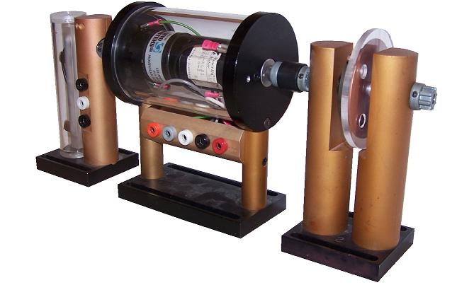
The basic plant for the controls lab is shown above. On the left is a potentiometer, shielded to keep hands away from live wires and to keep the connections intact. The potentiometer is a single turn pot. with approximately 340 degrees of electrical travel. In the middle is the motor/tachometer unit used to drive almost all the lab experiments. The motor is a Minertia Mini Series motor. A relatively cheap motor was used so that some friction would be present, introducing the students to the nonlinear effects of friction. The DC tachometer is rated at 3V/krpm. The module on the right is one of the possible flywheels used to add rotational inertia to the system. The mass of the flywheel can be easily changed by simply adding more black disks. A simple change to the flywheel ensures that lab results will vary from semester to semester, and minimizes cheating on labs.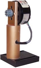 All modules have a similar baseplate, allowing each module to be bolted, via thumbscrews, to the optical breadboard at each bench. The baseplate is slotted, so that each module can be moved around slightly for adjustment, removal, or replacement. The modules are linked by rubber couplers. These couplers were used to allow for slight variations in the height of each module, which is nominally 4.5" at the center of the through-shaft. The electrical modules have banana jacks built into them, allowing connections to be made easily.
Shown above are the lab's optical encoder modules. The left encoder modules is used in place of the potentiometer, giving much finer position measurements. The optical encoder module on the right is used when a through shaft is required, as with a 6th order dual torsion-spring plant. The belt and pulley system of this module has a fair amount of friction and damping present, adding more degrees of complexity. Both optical encoder modules use DRC optical encoders capable of 5000 counts per revolution when quadrature encoding is enabled.
All modules have a similar baseplate, allowing each module to be bolted, via thumbscrews, to the optical breadboard at each bench. The baseplate is slotted, so that each module can be moved around slightly for adjustment, removal, or replacement. The modules are linked by rubber couplers. These couplers were used to allow for slight variations in the height of each module, which is nominally 4.5" at the center of the through-shaft. The electrical modules have banana jacks built into them, allowing connections to be made easily.
Shown above are the lab's optical encoder modules. The left encoder modules is used in place of the potentiometer, giving much finer position measurements. The optical encoder module on the right is used when a through shaft is required, as with a 6th order dual torsion-spring plant. The belt and pulley system of this module has a fair amount of friction and damping present, adding more degrees of complexity. Both optical encoder modules use DRC optical encoders capable of 5000 counts per revolution when quadrature encoding is enabled.
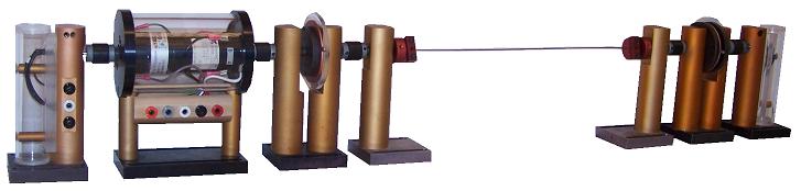 This is the 4th order torsional plant, most commonly used to demonstrate state-space design methods. Again the basic pot./motor/flywheel system can be seen on the left side. The next module is basically a clamp, with a piece of piano wire, functioning as the torsion spring, inserted into the jaws. At the other end of the torsion spring is another clamp, followed by a flywheel and another potentiometer for position feedback of the second disk. The gauge of piano wire used will vary the pole locations of the system. Simply changing the wire thickness between semesters ensures that controllers which worked in the previous semester will not work in the current one.
Preliminary designs of all the modules were created by Dan Block, Control Systems Lab Manager. The ECE Machine Shop contributed greatly to the final design and fabrication of all the modules.
This is the 4th order torsional plant, most commonly used to demonstrate state-space design methods. Again the basic pot./motor/flywheel system can be seen on the left side. The next module is basically a clamp, with a piece of piano wire, functioning as the torsion spring, inserted into the jaws. At the other end of the torsion spring is another clamp, followed by a flywheel and another potentiometer for position feedback of the second disk. The gauge of piano wire used will vary the pole locations of the system. Simply changing the wire thickness between semesters ensures that controllers which worked in the previous semester will not work in the current one.
Preliminary designs of all the modules were created by Dan Block, Control Systems Lab Manager. The ECE Machine Shop contributed greatly to the final design and fabrication of all the modules.
Why Modular?
Modular equipment allows every part to be interchangeable. This is a huge savings over buying specially made control systems models for every individual experiment. It also allows a great deal of latitude in the complexity of the system being controlled, while maintaining very similar systems at each bench. Reproducing results is easily accomplished, even if the students are working at a different station. The basic components of all the current plants include a potentiometer module, a DC motor/tachometer module, and a flywheel module. Additions to this simple system can include torsion springs, optical encoders, or extra flywheels.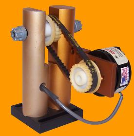
Through-hole encoder
University of Illinois
at Urbana-Champaign
306 N. Wright St.
Urbana, IL 61801