Robot Following
Catch me
if you can!!!
Catch me
if you can!!!
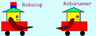
Starring: Roborunner, Robocop,
Dirk Reum
Jaideep Raje.
A Follower robot follows the path of the leader using vision and a positioning logic analogous to GPS.
Introduction.
A leader robot would travel along a certain path (Wall-following, figure 8, Circle or a Rectangle). A second robot can follow the leader using one of the following approaches.
1) Vision.
2) Position following through Wireless Modem.
3) Combination of Vision and Position following.
4) Offset Follow using Velocity and angle of the leader sent through Wireless Modem.
The leader moves in some fixed trajectory like wall-follow, figure 8, circle and rectangle. While doing this it sends information about its whereabouts to the follower. The information is sent through a Wireless Modem. The same Wireless Modem is used by the Follower to receive the information sent by the leader. A light is mounted on the leader to facilitate vision follow of the follower.
Selecting appropriate switch state on the DSP chooses a particular leader trajectory.
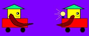
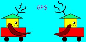
The follower robot follows the leader using one of the following modes. In vision mode, it does not need any information from the Leader. It simply follows the light source mounted on the leader. In position mode, follower receives the position coordinates of the leader through a wireless modem. These position coordinates are used by the follower to follow the leader’s trajectory.
Follower Modes.
1)
Vision
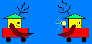
A light source is
fitted at the top of the leader robot. The Follower robot follows the leader by
maintaining the image of this light source within the centre of its picture
frame. The gains have to be designed in such a way so that the follower does
not loose the image of the light during a turn. Vision following works
precisely along the straight-line paths. Its accuracy and smoothness reduces
with an increase in turn. Thus for zigzag routes vision following looses
accuracy and becomes jerky.
2)
Position Following through Wireless Modem.
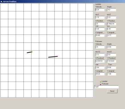
The position coordinates of the leader are sent through the wireless Modem using Visual basic to the follower robot. These position coordinates are stored in an array in the follower robot. The follower calculates the error between its current position and the oldest value in the array of position coordinates. This error helps to calculate the Control Effort. For this mode a delay of about 2 sec is given to the follower so as to fill the information array fully before it starts moving. A very important point to note in this mode is that we are not using any sensor in this mode so typically this has advantages in GPS application in vehicle motion etc.
Position following is precise, smooth and accurate. The turns made by the follower in position following are smoother than Vision Following. It however looses its accuracy over a period of time due to the drift in the Rate Gyro. The drift causes the follower to offset and eventually loose the leader path.
3)
Combination of vision and Position following.
The follower follows the light till it is seeing it. Once some dynamic obstacle comes in between the two robots, the follower will stop until the obstacle has gone and then position follows until it sees light again and starts following the light thereafter. Vision is the primary mode of following. When the follower looses the image of the light, position following takes over and continues till the follower again sees light.
The combination helps to gain advantages of both the following methods.
4)
Vref-turn following
In this mode the follower receives the information about the reference velocity and the turn of the leader every 300 milliseconds and follows this information. This mode is useful to duplicate the trajectory followed by the leader with some offset, like we can make the leader move in some trajectory like figure 8, circle etc and the follower can be made to move on the same trajectory at some other position.
Duplication of Trajectory is useful in Agricultural Engineering.
Wall-following
path using Vision mode video
Wall-following
path using Position following mode video
Figure 8 path using
Vision mode video
Figure 8 path
using Position following mode video
Circle path using
Vref-turn following mode video
Codes.
1)
Leader.
The leader code has algorithms for different trajectories and sends its positions to the Visual Basic interface through a wireless modem.
It can travel through the following trajectories depending on the different switch positions.
a) Wall-Following.
b) Figure 8.
c) Circle.
d) Rectangle.
Leader code (zip file).
2)
Follower.
The Follower code takes data from the Wireless Modem and processes this data to use in different modes of following the leader.
Follower code. (zip file).
Switch States.
1)
Leader.
Switch States on the Leader DSP are used to select an appropriate trajectory for the leader.
1) Circle: State = 14. Switch ‘0’ Down.
2) Wall-Following: State = 13. Switch ‘1’ Down.
3) Figure 8: State = 12. Switch ‘0’ & ‘1’ Down.
4) Rectangle: State = 11. Switch ‘3’ Down.
2)
Follower.
Follower mode is decided by the Switch States on the Follower Robot.
1) Vision-Position: State = 14. Switch ‘0’ Down.
2) Position: State = 13. Switch ‘1’ Down.
3) Vref-Turn: State = 12. Switch ‘0’ & ‘1’ Down.
Controls.
1)
Leader.
The leader has predefined velocities for different paths.
1) Circle: 2.50 tiles/second.
2) Wall-Following: 1.50 tiles/sec (along straight line), 0.4 tiles/sec (along the turn).
3) Figure 8: 1.25 tiles/second.
4) Rectangle: 1.00 tiles/second.
2)
Follower.
The follower uses
1)
PI control for Vision Following.
2) P Control for Position Following.
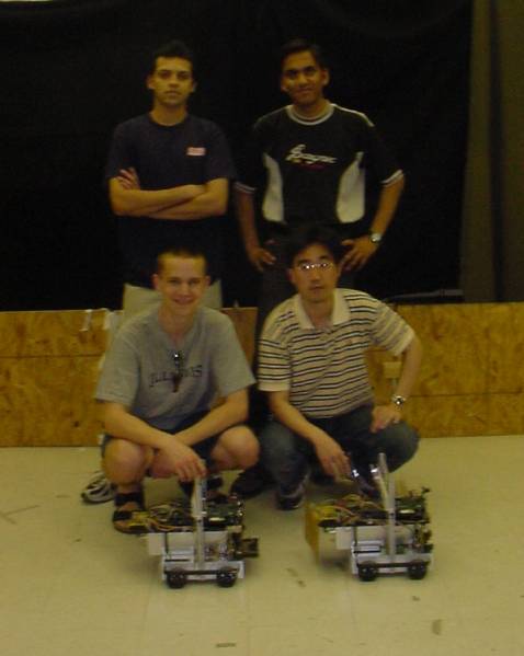
The Creators!!!!