OBSTACLE MAPPING AND
NAVIGATION
Goals | Overview
| Pictures and Video | Problems | Future
Improvements | Files
Group Members:
|
|
|
|


GE 330, Spring 2004
GOALS
The goal of this project was to equip a robot with the ability to roam around an area and create a “map” of where there are obstacles and where it is free to travel, then to provide the robot with the ability to travel to a user defined position on this created map. Our obstacles of focus are the walls of narrow corridors creating simple “mazes” (Figures 1 and 3 show examples). After creating such a map, the robot would be able to travel to any area of open space as directed by a user at a remote location. This has a multitude of applications from bomb disarming robots to rovers that will navigate the surface of other planets while controlled from earth.
OVERVIEW
The
project stemmed from an old version that interfaced with previously used
hardware in the Mechatronics course, which has since changed. As a result a large part of the project was
making this function with the new robots and their circuit boards. After converting the code to operate on our
robot we designed software to create an obstacle map and determine the correct
path for the robot to follow. These
tasks will be discussed in detail later.
ROBOT
The
robot is equipped with a set of ultrasonic sensors mounted to the top of the
robot that rotate so they can be used to map the environment in all 360 degrees
(shown in Figure 6). The rate gyro is
used to keep track of the robot’s location as it travels through the
terrain. The location of the robot and
the obstacles it “sees” are sent back to the user interface to monitor it.
USER INTERFACE
Visual Basic is used to monitor the robot based on its position and direction according to the map being created by it. Due to a problem with drift the operator must ensure that the robot’s bearing is correct, and when it differs from the actual manual correction is necessary. This problem is addressed briefly in the Problems section. Once the robot has provided sufficient data about its surroundings, the user can use this map to send the robot to any area of the environment and the robot will avoid all obstacles on its course. This is done by clicking on the goal position of the robot with the right mouse button (draws the green dot in Figure 4) and pressing the “Determine Path” button in the VB interface.
MODIFICATIONS AND ADAPTATION TO PREVIOUS CODE
As
previously mentioned the start of the project required us to adapt code written
for an old board. Differences between
this and our new board include accessing sensors and wireless transmission via
the modem. Also we implemented specific
functions in separate files to have more order in the system. Examples are PIVelControl and UART related
functions. We did not use the
correction readings that were used by the previous code, but instead used the
raw data readings from the Ultrasonic and IR sensors. We also made several significant changes to the VB User
Interface. It is now capable of sending
not only the manual correction of the robot’s bearing, but also the calculated
path for the robot to follow. Additionally
we added the capability of saving recorded maps and loading them again at our
convenience to recalculate the path.
TRAJECTORY PLANNING
In
order for the user to be able to tell the robot to travel to a given area of
the map, an algorithm must be implemented which will create a numerical
representation of the environment. We
chose to use the wildfire method, which is explained in detail below.
WILDFIRE
Our method of choice for determining the path of the robot through the terrain is Wildfire. Our procedure starts by labeling the cells of all obstacles, whose locations are determined by the robot, with the number 1. Wildfire then calls for the destination cell on the course to be labeled with a 2. From there, each unnumbered cell normal to a numbered one is subsequently labeled with a number one higher than the previous. After all relevant cells of the environment are numbered, the robot’s path is determined by telling it to travel from its start point to the cell adjacent with the lowest possible number. A major advantage of this method of path determination is that the robot can negotiate an area with an incomplete map, as long as the obstacles directly between it and the goal are mapped reasonably well and there is a general sense of the boundary obstacles. An example of incompleteness that is not a factor to the robot’s navigation can be seen in Figure 2, on the bottom edge of the map where there are large holes that do not interfere with our ability to correctly navigate the obstacles. The way we ensured that the robot would encounter as few problems as possible is by creating the path that contains the minimum possible amount of turns and only allowing the robot to perform right angle turns. We accomplished this by telling the robot to search vertically and horizontally for the lowest possible cell number. This will result in each leg of the robot’s path to place it as close as possible to the goal, and inherently minimize the amount of turns necessary. Once the turning points of the robot’s path have been calculated they are sent to the robot and followed.
PICTURES AND VIDEO OF ROBOT MAPPING AND NAVIGATING
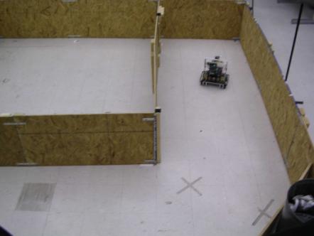
Figure
1: Robot mapping corridors – Map shown in Figure 2
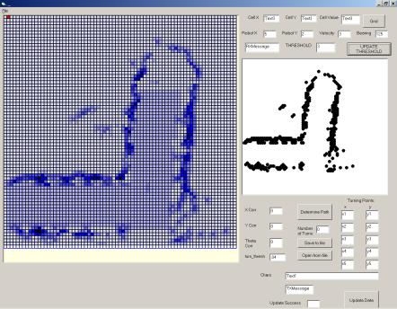
Figure
2: Robot’s map of environment with threshold map of obstacles
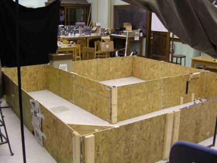
Figure
3: Complete view of environment mapped in Figure 2
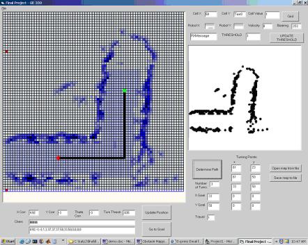
Figure
4: Map with calculated path displayed
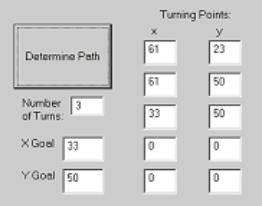
Figure 5: Calculated path for trajectory shown in Figure 4
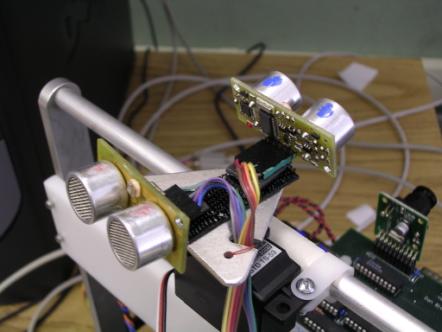
Figure
6: Rotating sensors mounted on robot used for mapping
PROBLEMS ENCOUNTERED
OVERCOME
Problems
arose mostly with respect to the navigation aspect of our project. Poor bearing readings resulted in the robot
steering off course, making accurate navigation exceedingly difficult. After adjusting the gain on the rate gyro
and restricting turns to right angles only (as described in our modified
wildfire algorithm) the robot was able to execute its turns and negotiate the
course with ease.
UNABLE TO OVERCOME
We
tried several different strategies of attaining accurate readings for the
bearing of the robot, including using the compass, rate gyro, and encoders in
the wheels, but never really seemed to be able to make good readings of the
angle of the robot. Rather than
overcome this shortcoming, we manually corrected the robot when it went astray
in order to successfully map the environment.
Mapping
large open environments is also not feasible with the ultrasonic sensors we
used because the range is less than necessary for a bigger space. This problem is indirectly related to the
problem with drift mentioned above in that the larger the area, the more
navigation is necessary while mapping, so the more error would be present
requiring a significant amount of manual correction.
IMPROVEMENTS FOR FUTURE AND CONCLUSIONS
We
were able to attain reasonably good maps of our environments and also navigate
them with some degree of precision with our designed planning scheme.
However,
several aspects of the project could have been better with a few improvements
to the system. First, using a more
powerful device to read the robot’s bearing could eliminate the drift. This component would eliminate the need for
continuous user intervention in the form of angle correction, and would allow
completely autonomous mapping. We would
have liked to use more than two sensors to perform our mapping, especially to
reduce the amount of time necessary. More
accurate sensors with larger ranges would improve the quality of the map. A camera could even be implemented with a
set of lasers to obtain obstacle distance information with extreme
precision. If a consistently accurate
bearing measurement was present, different methods of navigating the course
could be used providing more sophisticated paths, such as potential vector
fields or a standard wildfire method.
FILES WITH CODE
REFERENCES
Paper talking about wildfire algorithm
University research to be updated later.