|
|||||||
|
Objectives
Results |
|
||||||
|
|
|
||||||
|
|
Background
In order for you to get a better understanding of what is a Gyro and what is the cool effect associated with it call precession take a look at this great website: http://science.howstuffworks.com/gyroscope1.htm |
||||||
|
|
Design
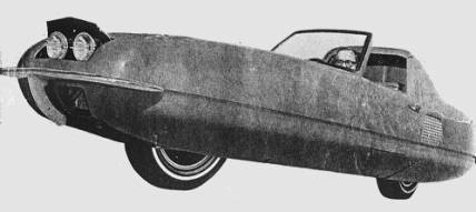
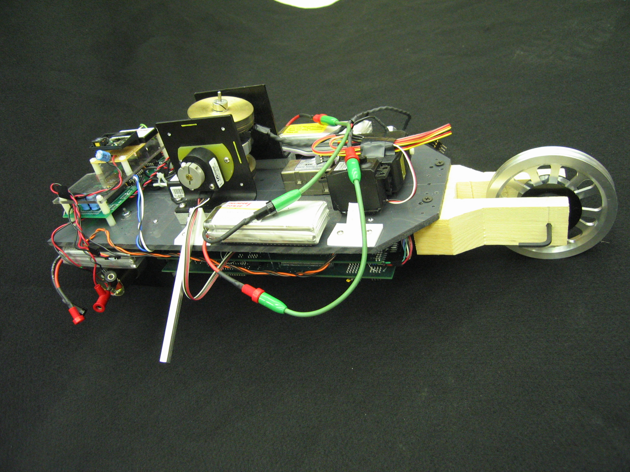
Our main idea for the design was to make this prototype look (in concept) like one of the gyro car developed on the 50’s and 60’s:
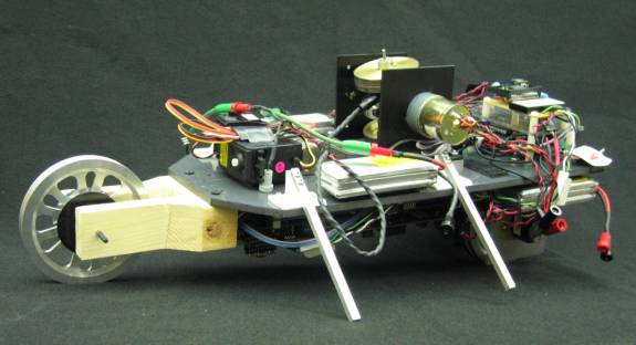
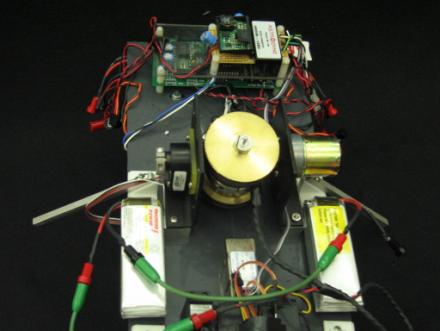
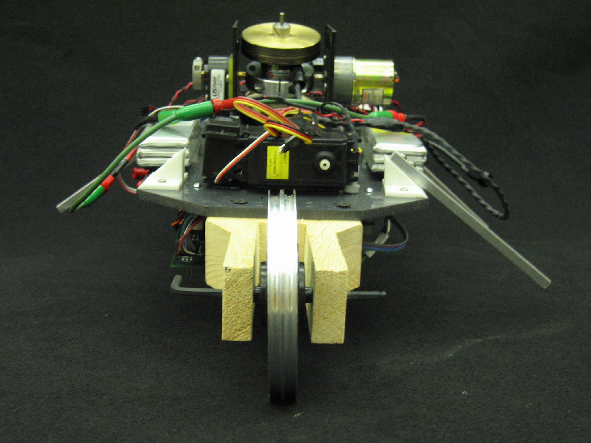
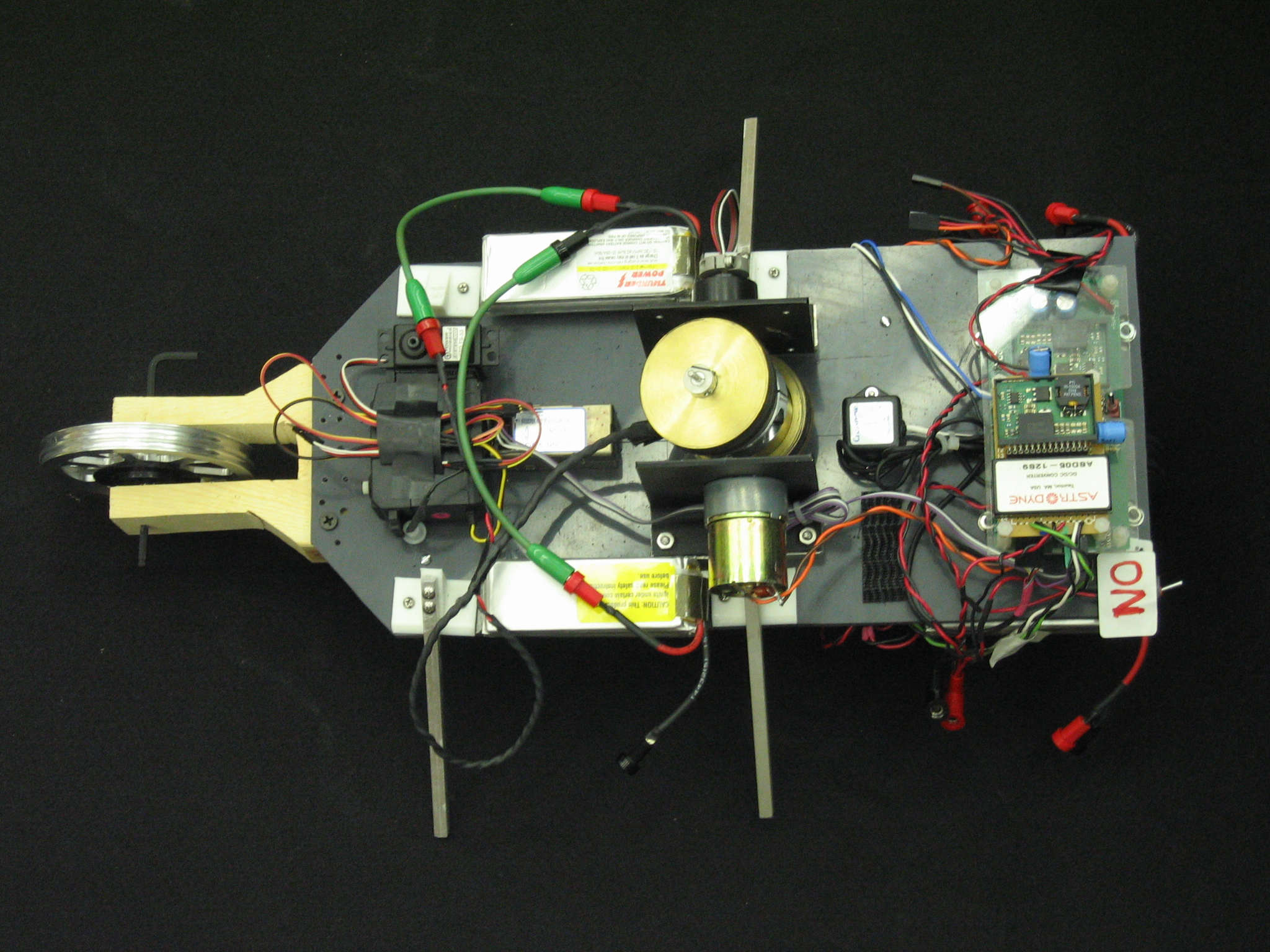
By the end we got something that looks more as a motorcycle. To start with we first developed the gyro and to test it, we put it on top of a plastic board balancing on some screws attached to the bard and did some experimentation with it and the first attempt of controller. Once we felt confident about some of the preliminary results we started the construction of the prototype. The first suggestion for the prototype robot was to put everything in the top part of a new plastic board of greater size that the one were using, with only the two wheels at the bottom. But after couple of sketches we realized that there was too much to put on only one surface (gyro, tilt sensors, DSP, amplifiers, batteries, RC-servos) so we would have to redistribute some weight in order for this to work. So, we decided to use all the surfaces available (top and bottom of the board) and at the same time make it self-balance. This idea turned out to be the best, not only because it almost balances itself but because it looks good too. After measuring, cutting, drilling, and screwing everything together, we ended up with a robot with all the necessary components to be automated. On the bottom part of it we have the two tires, a couple of batteries, and all the circuit boards (DSP and daughter cards). On the top part we have the tilt sensors (tilt and tilt rate), amplifiers, a couple of batteries, and of course, the gyroscope. Plus, we added some stands in each side for protection. We thought that it would be nice to have some steering in it. For that reason, we added two servos on the top-front part of the robot designed to move some sort of bracket connected to the front wheel. But because of our time limitation and some stability issues we decided to lock the front wheel for now. This explains for the rough piece of wood attached to the front wheel. In the figure below you can see some of the components of our gyro-car:
|
||||||
|
|
Controller
For the controller we implemented a control law with two components. The first component uses the information from the tilt and tilt rate sensors as feedback to create a precession torque to stabilize the gyro-car in case this one tries to fall on one of its sides. The generated precession torque is generated in the opposite direction in which the gyro-car is falling. The form of the controller is as follow:
For the second
portion of the controller we implement a simple PID controller to bring the
gyro to its reference point (normal spinning direction pointing upwards)
after it does a stabilization job with the first controller law we just
mentioned above. This part of the controller revives feedback from and
encoder attached to the axis perpendicular to gyro axis of rotation. The form
of this controller is as follows:
By combining those two control laws by hand tuning all the gains we were able to get a balance point between both controller permitting us to add both contributions and still get the desire results in terms of stability and in terms of time response for always be around our reference point for the gyro. |
||||||
|
|
|
||||||

|
Right Side |
Top Gyro |
|
Front |
All top |

Videos
:
·
Tapping
Conclusions …
The project was a success until the proposed point that it was not that ambitious. As future work during summer 2005 we will be working on the stirring mechanism and the stirring control. Also we may get a model for this prototype in order to apply some known control techniques to get desire behavior due to proposed specifications. So wait for next season if you want to find out for new results!!!
![]()
Team Members …
Dan Block

![]()
Fernando Class


Juan S. Mejia


Thanks to …
Everybody at UIUC Mechatronics Lab, including Professor, instructor, TA’s, and classmates!

Important and interesting links …
http://www.dself.dsl.pipex.com/MUSEUM/TRANSPORT/gyrocars/gyrocar.htm
http://science.howstuffworks.com/gyroscope1.htm
![]()
C Code (Have
fun with it) !!!
Zip files with code
(Download)
![]()
![]()
Visitors

![]()
![]()