Ultrasonic Position System
The ultrasonic position system uses ultrasonic transmitters/receivers to triangulate position of the robots used in GE423. Each of three transmitters uses a distinct frequencies: 23 kHz, 31 kHz, and 40 kHz. The 2812 DSP is used to measure signal timing and calculate position based on these values. The design of the electronics, as well as discussion of the software development is presented below. The electronics were not intergrated with the 6713 DSP on the robot.
Note: To get around the issue of clock syncing, the robot will start in a known position, and calculate position for four cycles before proceeding. An alternative to this would be to add a fourth transmit frequency and use the 4th signal to sync the robot clock with the transmit clock.
1.0 Hardware
A wide variety of hardware was used for this project. The hardware was chosen based on availability and price. By no means is the solution presented "the best"or the only way to achieve the desired results, but it is a workable solution.
1.1 Ultrasonic Transmitters/Receivers
The ultrasonic sensor were purchased from Massa. The TR-89/B series where chosen because they come in 3 different frequencies, and they were stock parts. There is no pdf data sheet available on the Massa website, all information if available here. The main drawback of using Massa is there $500 minimum order, and the sensors aren't cheap at about ~$30 each.
1.2 Transmit Circuit
A schematic of the transmit circuit looks like:
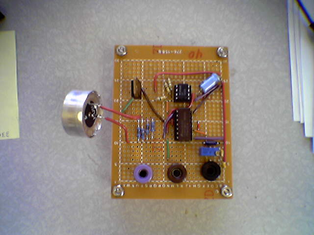
Images of the perf-boarded transmit circuits:
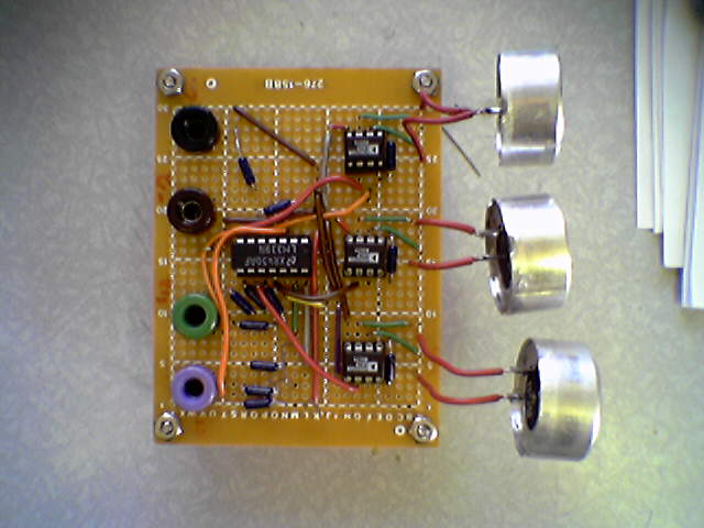
Details on the components of the transmit circuit can be found in the subsection below:
1.2.1 Frequency Generation
The transmit circuit take from the Massa Website looks like:
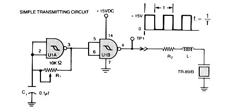
Source:http://www.massa.com/datasheets/graphics/tr89_data.gif
Where R1 is a 10k 10 turn precision wound potentiometer, and U1 is a CD4039B NAND Schmitt Trigger. The tuning resistor R2 and L where left out to increase the transmit power around the base frequency. The potentiometer was adjusted until the frequency was the desired base frequency. A 1k resistor was added in parallel with the potentiometer to give a higher resolution. For the 40 kHz case, a smaller capacitor was required to reach the base frequency. Make sure to tune the circuit with the ultrasonic transducers attached, because the additional impedance will change the transmit frequency. The 12 Vdc was generated by a lab supply.
The output at point TP1, is a 12V peak to peak is a square wave at the desired frequency. The point TP1 was connected to the Driver Signal Circuit presented below.
1.2.2 555 Timer Circuit
The documentation for the 555 timer can be found here. An a picture of how it is wired can be seen below:
Source:http://www.williamson-labs.com/480_555.htm
Using the handy calculator for Ra, Rb, and C found here, Ra=100k ohm, Rb=200k ohm, and C=2.2 mircoF.
1.2.3 Driver Signal Circuit
The 35 Vdc supply is manufactured by Ultravolt, part number 1/4Aa24-P30. This supply is actually a 0-250 Vdc supply that uses a potentiometer to control voltage output.. The transistor used is an IRF520 n-channel MOSFET.
1.3 Receive Circuit
A block diagram of the receive circuit can be seen below:
And a picture of the perf-boarded receive circuit can be seen below:
Details on the components of the receive circuit can be found in the subsection below:
1.3.1 Low Signal Amp Circuit
An instrumentation amplifier made by Analog Devices was used to amplify the low signal output of the ultrasonic receivers. The actual part used was the AD620, one is recquired for each receive channel. Analog has a nice tool here, to size the gain resistor, Rg. Based on experiments, a gain value of 33 was chosen, resulting in a Rg of 1.5k ohm. The AD620 was wired as follows:

Source:http://www.analog.com/images/Product_Descriptions/3888333375812882340AD620_fbs.gif
1.3.2 Comparator Circuit
The analog comparitor used was part number LM339. The volatage divdier was powered using +5 Vdc to creat the digital level output signal. The output from each instrumentation amplifier was wired to the "+" terminal, and the "-" was wired to 3 volts. The 3 Vdc signal was created from the +15 Vdc supply using a voltage divider. The output of the comparitor was wired to a 5 Vdc via a 3k resistor.
2.0 Software
The timing of the hardware interrupts from the 2811 is calculated, and from the times, position is calculated in the 2D plane using a combination of least squared fit and Jacobian iteration.
2.1 Matlab Triangulation Code
The first algorithm was developed using Matlab. This code can be found here. The algorithm is not stable for all input parameters, a good set of test conditions are:
[x,y]=blah(.010,.012,.012)
[x,y]=blah(.009,.014,.012)
[x,y]=blah(.011,.011,.011)
Note the highly descriptive function named blah
2.2 DSP C Code
The c code for the 2812 DSP is in the attached zip file. The code works as following:
- Hardware interrupt pin get triggered
- Record absolute clock time when pin transition occurs
- Go back to step 1,and once all three pins have been triggered:
- (only do this step the first time through the code) Assume robot stationary, acquire base transmit period for each frequency by averaging first 4 values, this step syncs the clocks of the transmitters to the robot
- Calculate time from transmitter to robot for each frequency
- Triangulate position of robot using least squared fit to data points
- Wait for fixed amount of time, ignore hardware interrupts during this time because of the nature of the transmit signal
- Go back to Step 1
3.0 Lessons Learned
- A resistor was needed in parallel with the tuning potentiometer to give better resolution
- A resistor was required in parallel with the US transmitter for the circuit to function because the transmitter is like a capacitor.
4.0 Acknowledgments
Various people and online resources aided in this project:
- GE423 Lab Instructor: Dan Block
- GE423 TAs: Dave Johnson, Daniel Herring
- My officemate: Steve Tschopp
- Misc. Consultation: Tim Cargol
- Misc Websites:
- http://ourworld.compuserve.com/homepages/Bill_Bowden/555.htm
- http://www.williamson-labs.com/480_555.htm
- http://www.massa.com
- http://www.digikey.com (source for datasheets)