Kevin and Kristen’s Awesome LCD Display Website
***** 1 - What we have *****
The color LCD module was obtained from
http://www.sparkfun.com/commerce/product_info.php?products_id=569
This site has two documentation links; one is a PDF for the Epson LCD controller, and the other is some sample SPI code for another microprocessor. Based on this information, we have developed some sample code to control the LCD using our DSP.
***** 2 - Hardware needs *****
Currently, we power the LCD by hooking it up to a 3.3v programmable power supply. When turned on, the display draws 160mA. Small variations in this voltage cause the display brightness to change, causing flicker. Therefore, we need a new circuit which can regulate the robot's main 5v supply to 3.3v and filter this enough (big capacitor?) to eliminate flicker.
***** 3 - Software needs *****
Right now, we know how to turn on the display, set the colors and brightness, and draw to the screen. Now, a user library is needed to simplify its use; it's interface might look like
The camera will first be setup using the spi and later DMA will be used so the camera can be interfaced with other devices.
***** 4 - Software notes *****
The LCD display natively uses 12-bit color, but the controller provides two color modes. In 8-bit mode, each pixel is a separate byte, and the display controller uses a lookup table to convert rrrgggbb to rrrrggggbbbb. In 12-bit mode, pairs of adjacent pixels are sent as a 3-byte sequence of the form (rrrrgggg, bbbbRRRR, GGGGBBBB), where rgb are the first pixel and RGB are the second. For speed, we will be using the 8-bit color mode.
The color camera code represents each pixel as 3 bytes, one each for red, green, and blue. To display the picture, a conversion will need to be done to convert these groups of 3 bytes into one byte of rrrgggbb data. This could be done using lookup tables, or maybe more efficiently using bitwise operations such as addition, or, and shift.
To write to the screen, one calls PASET and CASET to specify the starting (x,y) coordinates, and then the pixels are set by sending data after a RAMWR. Sending the full 128x128 image or even a 88x72 picture takes a lot of time. The DSP has a feature called direct memory access (DMA) which can stream chunks of memory over the SPI port and free up the DSP to do other tasks. Thus getting this to work is a high priority.
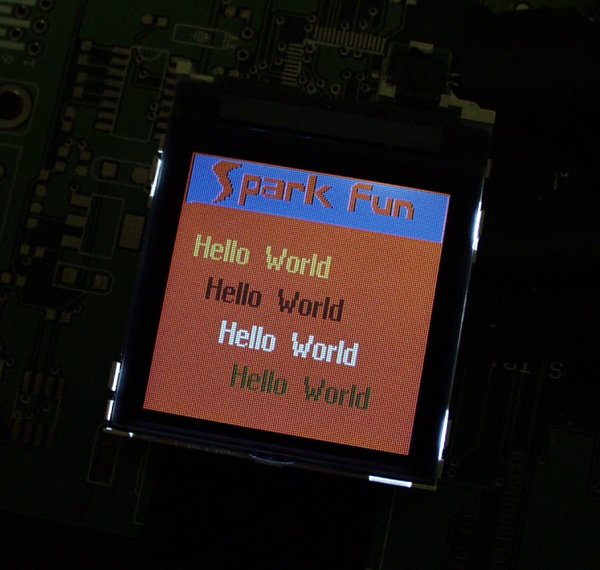
The current (black & white) LCD display has a built-in character generator. This allows us to print "hello" by sending it a sequence of ASCII character codes, and it knows how to make the letters look right. The color LCD display does not have a built-in character generator. Therefore, code must be written to convert the graphic symbol '!' into an array containing the states of the 8x8 pixels...
******Text****************
Code composer takes a string from VB containing a message and a location on the screen in the function Get_Message(). This function then separates the string into characters and identifies the xo and yo coordinates for the text, which is the top left corner of the first character on the screen. This function then calls mem_print_line(). Here, init_LCD_mem is called to start writing to the EDMA. Then, the text wrapping function checks to make sure the characters that are printing are at valid locations on the screen, and if they are not it adapts, this goes on through each character in the string. Within this function after placing each letter, process_letter() and mem_print_letter() are called. process_letter() uses an array which corresponds to the ASCII character set. This array was created by scanning the character set in a line eight times from top to bottom, using eight bits per letter across. This means the character will be an 8x8 pixel image. Process_letter() uses this array to find the relevant entries of the array for the corresponding character. Them mem_print_letter takes the array created in process_letter and integrates the background and foreground colors to create a 8x12 set that is stored in the EDMA for each letter in a unique location. Once it is set here, when the EDMA is called to output, all the text information will be set in the appropriate position.
Notes
***The text wrapping function is written in terms of a video location video_x and video_y , so if the video image is ever moved (in future coding) in terms of these coordinates, the text will wrap around it.
***Background and foreground colors are set as global variables.
******5- Our Logic********************************
Two different methods of transferring data were used in the project. The first method used a S.P.I Serial Peripheral Interface. This is a device with basically three lines; a clock, a chip select, and I/0. It is used to communicate between the camera and LCD display with commands like SPI_command and SPI_data. This method works well and sends data rather fast. However, the SPI requires the DSP be used only for it, so the DSP cannot be used to run the servos or perform any other function.
In order to get around this, an EDMA chip is used to allocate memory. This chip can access a place in RAM and store data. Essentially, it is capable of performing all of the DSP’s capabilities but processing data. Memory is allocated and registers for Event E are setup so that the EDMA knows where and how much memory it is accessing.
1) The Camera gets images in real time and places it inside its memory. When the camera has a full image, the interrupt 6 pin goes low, and a signal is sent to the DSP
2) In EDMA the DSP will not do the job of allocating the memory or accessing locations in RAM. Instead the EDMA chip will setup a location in memory and put data from the camera inside. This memory allocation is done inside my_dspvisioncolor50Hz.c
//************Allocate LCD MEMORY*************
LCD_mem = (short int **)MEM_alloc(SDRAM,LCD_mem_rows*sizeof(short int *),0);
if (LCD_mem == MEM_ILLEGAL) {
*(unsigned volatile int *)IO_PORT = (0x2)<<24; // Turn off LEDS
SYS_abort("Memory allocation failed!\n");
}
LCD_mem[0] = (short int *)MEM_alloc(SDRAM,LCD_mem_rows*LCD_mem_cols*sizeof(short int),0);
if (LCD_mem[0] == MEM_ILLEGAL) {
*(unsigned volatile int *)IO_PORT = (0x2)<<24; // Turn off LEDS
SYS_abort("Memory allocation failed!\n");
}
for(i=1;i<LCD_mem_rows;i++) {
LCD_mem[i] = LCD_mem[i-1] + LCD_mem_cols;
}
init_LCD_mem();
//************************
3) When the DSP receives interrupt 6, it tells the EDMA that it can take data from the camera and put it inside its memory.
4) When the EDMA has placed a full image in memory, interrupt 8 is called. Because of this the DSP knows it can start processing an image.
5) The DSP must first set a flag to let the EDMA know when it is working on an image and when it can receive new data. If the flag==0 the EDMA knows that it can send over an image for the DSP to compress.
6) The user_Process_Colorimagefunc function is used to place data into a location in RAM LCD_MEM.
7) The EDMA will take data from memory 16 bits at a time and then place it on the LCD display through the SPI.
8) When the EDMA has sent over a full image to the LCD it triggers interrupt 8, letting the DSP know that it is ready for more data.
*************Our Code***********************************
C Code VB Code