Spring 2006
Mapping Robot
Project Description:
We created a program for the robot that creates a map of a course using infrared sensors as well as a laser distance sensor. These sensors combine to provide x and y coordinates of detected obstacles that then reference an array which is updated with whether an obstacle was detected.
A special robot provided by Dan Block was used for this task. This robot has side encoders that allow for very accurate angle measurements. This has been very helpful, since using the angular accelerometer in previous labs made finding relevant angles very difficult.
Mapped course for one run
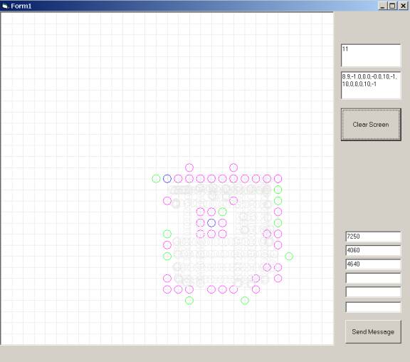
Gray circles = actual robot position
Magenta circles = Left IR sensor
Green circles = Front IR sensor
Blue circles = Right IR sensor
Nicholas Fezie: The Map
My part of the project was to create the map and initial search patterns. This involved creating an array representing the course that was then updated with the sensor readings as they were updated. The array was initialized to 0 and then as sensor readings returned x and y positions of obstacles, the element of the array was incremented. The value of any element in the array represents the likelihood of an obstacle being present. Each element of the array represents one tile to simplify understanding of the code. Sensor readings are rounded down to the tile before updating the array.
The sensor readings must be gathered, tested for meaningfulness, then converted to x and y coordinates based on the position of the sensor on the robot and the position of the robot on the course. These readings are then sent wirelessly to Visual Basic for later use.
There are 2 main ways for the robot to navigate the course. The first way implemented was a simple avoidance code where the robot would try to keep the IR sensors away from obstacles and move straight when no obstacles were detected. This mode was useful for testing the basic sensor readings but would be unsatisfactory for a true mapping task. It was decided to then pursue a square wave pattern that covers the course to increase the likelihood of covering the entire course. Once the robot reaches the opposite corner of the course from where it starts, the robot then turns and starts another square wave pattern rotated 90 degrees from the first. The square wave pattern behavior is coded through the use of a “switch” statement. Once the robot has completed the square wave traversal of the course, the robot finds the tile in the course array with the highest likelihood of an obstacle being present, not considering the wall. After finding the tile, the robot turns until it faces the object then drives until it is at the x and y position of the object (or stops when it gets too close to the object)
The final part of the project is a Visual Basic program that receives the sensor readings x and y positions and then plots them on a representation of the course.
Robert Koch:
My task was to determine a method of obtaining a more accurate angle measurement using the code and devices provided by Dan. Basically, three methods of obtaining an angle were provided. The first method was through use of the rate gyro. This method had been used in previous labs and had been found to have some problems because of ‘drift’ in the rate gyro. This problem caused the angle measurement to become corrupted soon after the robot was turned on. A second method used the motor encoders on the robot wheels to provide readings that could then be used to calculate the x-y position of the robot as well as the angle. This method would require some additional work because the robot is tank driven, meaning the wheels slide when it turns. The final method used extra encoders that were placed on either side of the robot halfway between the wheels on each side. The wheels driving these encoders would not slip and therefore provided the most accurate measurement.
Using the code Dan provided, I was able to experiment with the various angle measurements that were available. I found that using the extra side encoders, a very accurate angle could be provided. The quality of this measurement was very easy to observe using the Visual Basic portion of the program. While the robot followed the square-wave-pattern, it was easy to observe that parallel portions of the path indeed were represented as such in the VB map. Before, when we used the rate gyro to create the angle measurements, the user could easily see the corruption of the data after only a few turns had been made. Since neither the robot motor encoders nor the rate gyro gave as accurate of data, I decided to use the side encoder angle reading on its own.
The rest of my work included helping Nick write and test the code that made the other portions of the project function correctly. I suggested using an additional square wave path rotated 90 degrees in order to better determine the size and shape of the obstacles. I also thought we might be able to show the usefulness of saving the array on the DSP by traveling to the obstacle after completely mapping the course.
Dillon Yoshitomi:
My assignment within the project was to write code for a laser-web camera distance sensor. A paper was provided in which the formulas for calculating distance from the position of the laser dot, in addition to code that integrated the laser pointer-color camera device into the robot, and provided a vertically stretched sliver of the camera image. The goal was to add a sensor which had better accuracy at farther ranges than any of the other sensors (IR, Ultrasonic) normally on the robot. In the paper provided the author had achieved less that 1% error at ranges up to 2 meters, which became the target accuracy.
The code I wrote was a switch statement in the vision processing function that is called every time a new color image is received by the DSP. A subtractive method was used in order to be able to accurately differentiate between the laser and background red in the color camera image. Thus, a sliver of the image was stored with the laser off, the laser was turned on, and the code waited for two images before the stored image was subtracted from the current image to eliminate the background red. The centroid of the laser dot was calculated, and the value of the angle was calculated by assuming a linear relationship between the centroid’s position in the image and the angle from the camera lens to the laser dot. The distance from the camera to the surface which the laser dot was on is calculated by dividing a constant by the tangent of the angle.
The three difficulties encountered were determining constants for the linear relationship between angle and y-position, improving accuracy, and using the laser while the robot was moving. By looking at the curve of 5/Tan(angle), it could be seen that it was important to keep the value of the angle within a certain range to better reflect the actual variation of angle with range, and the constants were then determined by trial and error. Improving accuracy was related to the previously discussed problem, but was also affected by the waiting period between turning on/off the laser, and collecting the image. Again by train and error, a more accurate waiting period was determined to be two image cycles. And finally, attempts to use the laser sensor while the robot was turning were foiled because of the long cycle time for each distance calculation. In the time period between storing a background image and storing a laser on image, the section of the surface which each image had taken would be significantly far apart (so the two images were not of the same thing) and so the calculated value for distance would be incorrect. This was avoided by not taking laser measurements while the robot was turning.
Video: View from the Side, View from Above