Parking
Garage Robot
Team Members:
Greg Wittendorf (Objective 1)
Jon Kocher (Objective 2)
Scott Block (Objective 3)
Resources:
1. Mechatronics Robot
2. Color Camera
3. 5 LED’s
4. 7 IR Sensors
Project Objectives:
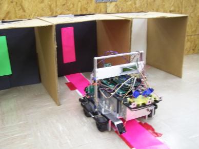
- Park
in and back out of three garages. Each garage has a unique color to guide
the robot into and out of the garage using color camera.
- Follow
a “road” out of the garage. Use color camera to recognize the road and
follow the road. Also incorporate
signal lighting on the robot to show when robot is turning, backing up as
well as headlights to come on when light intensity is low.
- Avoid
an obstacle placed on the road.
Project Solution:
- To
park in the garage, I first hard coded the displacements necessary to
place the robot in front of each garage from the road. This was
accomplished by creating a variable called “garagenumber”. When
garagenumber is 1, the robot will orient itself in front of the first
garage, when garagenumber is 2, the robot will orient itself in front of
the middle garage, etc. Once the robot is oriented in front of the garage,
it is guided into the garage by the color camera and the strip of color at
the back of the garage. Since each garage has a unique color to guide the
robot in, our code is able to search for each unique color.
To back
out of the garage, a variable called garage is set to 1. This tells the robot
that it is currently in the garage and needs to back out and find the road. The
robot also uses the variable garage number to know which garage it is in. The
strip of color at the back of the garage guides the robot out of the garage.
When the robot is a certain distance out of the garage, it then turns to the
road and starts road following.
While the
robot is road following, a marker is created in front of the garage that tells
the robot it is time to park in a garage.
2.
First, the signal lighting
will be explained. The lighting
resembles the functional lighting that is present on a car. A white backup LED is placed at the rear of
the robot and is switched on when in reverse, and off when going forward. Rear turn signals were also implemented into
the robot. They were programmed to
blink every 0.5 seconds if the robot is turning at a significant speed. Of course, the lights blink appropriate to
the direction turning. LED Headlamps
were also manufactured to using flashlight reflectors. These are active when the light intensity
sensor is less than a certain value.
Accordingly, the headlamps turn off once the value is greater than the
threshold set.
Once
the robot exits the garage. It stops
for a short period of time to collect data.
This is due to the fact that the color camera is mounted at the top of
the robot and the shortest distance in which the camera can see the floor is
approximately 2.5 ft. To account for
the data entry, the camera records data into an array and uses it after a
delayed amount of time. The time
variable is called buffinit, and iterates every 25ms down from 125 to 0 to
record the camera data into the array, cameraxbuff. The camera is set up to find the center of the pink road object.
It is also programmed to threshold the pink color from each other color to only
see the road. The color camera then uses
the data it retrieved a short duration (a few seconds ago), and follows the
course with a delay. The array fills
from the 125th cell and releases from the 1st cell. Camerabuff_size is a constant set to
determine how much of a delay is used.
At the end the project the Camerabuff_size equaled 20, which is only a
0.8 seconds delay. If the camera loses the pink road, the robot turns right
until it finds it again.
3.
The idea is to see an object
directly in front of the robot during road following and avoid it. This
was accomplished 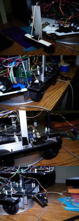 using a set of 3 IR sensors nick named “radar.” The 3 IR sensors were placed on a
platform. They were placed about an inch apart to provide a wider
sweep. The IR sensors only fire ever 70ms, which can cause blind spots if
the IR sensors are moving too fast. There are two ways to minimize blinds
spots; first put more IR sensors, and second get IR sensors that can fire
faster. So in this case more IR sensors were used to ensure that the
robot would see the object. The plat form was then attached indirectly to
a servo that is capable of moving from 0° to 180°
in less then 0.6 seconds. A gear system was used to reduce the swing of
the platform from 0° to 90°. The platform was angled
so when it is in the middle of its motion it is point strait forward.
Also the full range of motion was not used. The platform moves from 10°
to 80°. In one sweep each IR sensor pings the field of
vision 10 times (10° to 80°). So in one complete
cycle there are 20 pings and since 3 IR sensors are being used, 60 pings will
be sent out cycle (10° to 80° to 10°).
The radar is setup to complete one cycle in 2.8 seconds. This could be
sped up to about 1.2 second per complete cycle, but when the swing is faster
the less likely an object is to be spotted. For example, if you ran it
twice as fast only 30 pings would be send out for one complete cycle. For
the speed that the robot is running at the speed of the current setup of 2.8
seconds per cycle is plenty fast. Once the radar has spotted the object,
it will jump into object avoidance code. The first thing the robot will
do is turn 90°to the right and then drive till the rearmost IR sensor see
the object. It will continue to drive till the rearmost IR sensor loses
the object. After it losing the object the robot will drive strait for an
additional ~0.25 tiles. It will then turn 90°to
the left and drive forward till the rearmost IR sensor sees the object.
Once again the robot will continue to drive strait till the rearmost IR sensor
has lost the object and an addition ~0.25 tiles. During this pass, the
left-collision IR sensor is set to keep the side of the robot from colliding
with the object it is passing. Due to not slipping as much as normal
during turning, sometimes the robot makes a very tight turn and will hit the
object. The left-collision IR is slightly angled and set to a given
distance. So if the object falls with in that range the robot will turn
right till the object is out of the zone. This turning is always small if
it does happen. So back to when the robot clears the object, it will now
turn 90°to the left. This time it will use the mid-left IR
sensor to find the object. As soon as it finds the object the robot will
turn 90°to right and wait for 5 seconds. The 5-second wait is
to account for the robot regaining vision data.
using a set of 3 IR sensors nick named “radar.” The 3 IR sensors were placed on a
platform. They were placed about an inch apart to provide a wider
sweep. The IR sensors only fire ever 70ms, which can cause blind spots if
the IR sensors are moving too fast. There are two ways to minimize blinds
spots; first put more IR sensors, and second get IR sensors that can fire
faster. So in this case more IR sensors were used to ensure that the
robot would see the object. The plat form was then attached indirectly to
a servo that is capable of moving from 0° to 180°
in less then 0.6 seconds. A gear system was used to reduce the swing of
the platform from 0° to 90°. The platform was angled
so when it is in the middle of its motion it is point strait forward.
Also the full range of motion was not used. The platform moves from 10°
to 80°. In one sweep each IR sensor pings the field of
vision 10 times (10° to 80°). So in one complete
cycle there are 20 pings and since 3 IR sensors are being used, 60 pings will
be sent out cycle (10° to 80° to 10°).
The radar is setup to complete one cycle in 2.8 seconds. This could be
sped up to about 1.2 second per complete cycle, but when the swing is faster
the less likely an object is to be spotted. For example, if you ran it
twice as fast only 30 pings would be send out for one complete cycle. For
the speed that the robot is running at the speed of the current setup of 2.8
seconds per cycle is plenty fast. Once the radar has spotted the object,
it will jump into object avoidance code. The first thing the robot will
do is turn 90°to the right and then drive till the rearmost IR sensor see
the object. It will continue to drive till the rearmost IR sensor loses
the object. After it losing the object the robot will drive strait for an
additional ~0.25 tiles. It will then turn 90°to
the left and drive forward till the rearmost IR sensor sees the object.
Once again the robot will continue to drive strait till the rearmost IR sensor
has lost the object and an addition ~0.25 tiles. During this pass, the
left-collision IR sensor is set to keep the side of the robot from colliding
with the object it is passing. Due to not slipping as much as normal
during turning, sometimes the robot makes a very tight turn and will hit the
object. The left-collision IR is slightly angled and set to a given
distance. So if the object falls with in that range the robot will turn
right till the object is out of the zone. This turning is always small if
it does happen. So back to when the robot clears the object, it will now
turn 90°to the left. This time it will use the mid-left IR
sensor to find the object. As soon as it finds the object the robot will
turn 90°to right and wait for 5 seconds. The 5-second wait is
to account for the robot regaining vision data.
Videos:
Parking, Road Following, and Signal Lighting Video
Code: