STRATEGY
Our group's strategy is based on 15-20 different states to navigate through the
course and handle different tasks. The more complex tasks like picking up
a can, and collecting golf balls require separate functions.
We use the sensors on the robot for different things:
Infrared: Right wall
following and wall avoidance when lost
Ultrasonic: Used for precise stopping distance
threshold - more reliable for longer distance
measurements (3-6 feet) than IR.
LADAR: Used as a more
accurate distance measurement sensor, adjustable in the way
that we can change in code the
angle relative to the robot where we need to
know distance.
LADAR
Our group uses LADAR as a general purpose distance measurement on each side of
the robot, mainly used for finding the way out of the course if the robot is
lost.
![]()
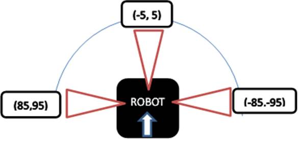
The LADAR will be used to find the distance to the right, front, and left walls
by looking at the average distance values from -95 to -85, -5 to 5, and 85 to
95 degrees respectively. The robot can ‘find itself’ based on what
these expected values are in certain cases. For example, if LADAR
distance to the left is more than twice the distance to the right, this may
indicate a wall to the right and nothing to the left.
SODA CAN
In order to locate and grip the soda
can, our group utilized the data obtained from the camera attached to the
robot. When a sufficient number of red pixels were found, the robot
turned until these red pixels were centered at a certain pixel location
corresponding to the angle at which the can must gripped. The robot then
drives forward until the same red pixels are below a certain pixel height
corresponding to the position of the gripper. Once the can has been
gripped, the robot proceeds to the drop off location while simultaneously
scooping up golf balls. In order to place the can, the robot uses camera
data to properly orient itself towards the pink sign. The robot drives
forward until it is at a certain distance from the wall as measured by the
LADAR data. Once the robot is in the correct position, the robot places
the can in front of the pink sign.
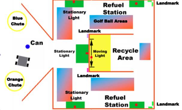
LOST ROBOT
Before the robot can reset its
location, it must first determine that it is lost. This is done by
checking for unusually large gyro readings when the robot is not moving.
If the robot is picked up and moved to a random location in the course, the
gyro readings will cause a flag to be set which will cause the robot to begin
its attempt to determine its position. The robot spins around at a
constant speed while looking for landmarks in the course, particularly the
pieces of green construction paper. These landmarks can be seen on the
image below.
![]()
![]()
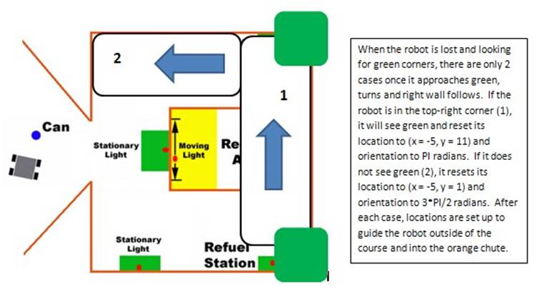
If the robot sees any green pixels, it will drive towards the green object
until it determines that it has reached a wall using an IR sensor mounted at
the front of the robot. The robot will then begin to right wall follow
until it reaches the next corner in the course. At this position, the
robot can reset its position by checking whether there is a landmark at this
location. Once the position has been set, the robot can proceed to drive
out of the course using the newly found position.
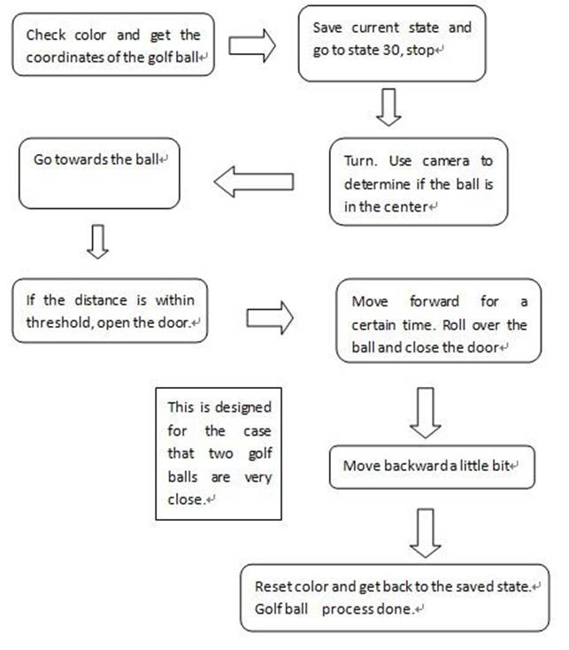
Finding
and Collecting Golf Ball Process
Block
Diagram
![]()
CAMERA USAGE
There are 5 states for Camera. At the very beginning, State
0 is used to search for Red soda can. After picking up the soda can, the camera
is set to State 1 to look for the first white light and two lights on both
sides. State 4 is set immediately when the robot knows which direction to go.
State 4 is used to search for the golf ball on the way. Only in State 4 will
the get_golfball function be called. When robot is in
the Recycle Area, State 2 is set to look for pink. On the way back, State 4 is
always set to get golf balls.
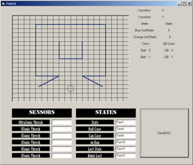
VISUAL
BASIC
The visual basic has been set up to look like the course and show where the
robot is using a circle. Using the Wireless Send function, the position of the
robot, the state, the color of the last golf ball, how many blue balls have
been picked up, how many orange balls have been picked up, and the position of
the last golf ball picked up are shown in the visual basic. The ability to send
control gains and ultrasonic thresholds to the robot have
also been implemented in the visual basic. Using an if
statement, the state is checked for state 9, which is the state after the can
is placed down. A cheerful sound is played to denote the successful placing of
the can. A sound is also played during startup of the visual basic application.
The position of the robot is used using geometry. The color of the last golf
ball is determined by which door was opened on the robot, which is ultimately
determined by the camera. The position of the last golf ball is sent through
the Wireless Send function when the robot is directly over the golf ball
pulling it into the door.
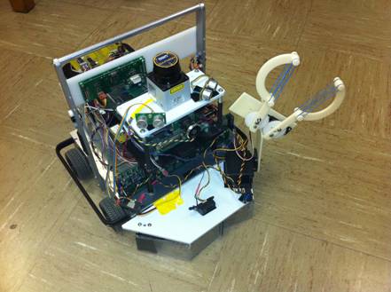
MECHANICAL

For the final contest, our group designed a gripper to pick up a soda can and
two doors to collect golf balls. Flags are set during certain states and
used in a servo function to increment or decrement each servo angle in order to:
- open or close the gripper
- hold up or hold down the arm
- close or open the right door
- close or open the left door
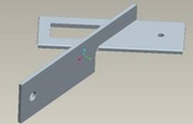
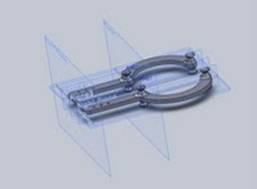
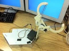
Gripper:
The gripper is made using a rapid prototyping machine and contains two servo
motors. The larger of the servo motors is used to move the gripper up and down.
The smaller servo motor is used to open the gripper open and close it shut. The
smaller servo contains a gear attached to it, so that when it rotates, another
gear attached to the other side of the gripper rotates, which opens and closes
it. The gripper is used to pick up the red can and place it down near the pink
cardboard sheet.

Doors:
The doors are made from cut plexiglass, hot-glued
together. The servos controlling door angles are mounted right-side-up
for as a convenient design solution and a divider in the middle is mounted to
the bottom of the front plate to separate the golf balls.
Prototypes:
Gripper
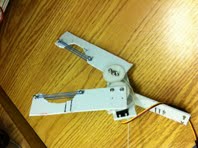
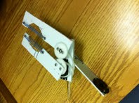
Initial
Model Design
Team
Carl Darukhanavala; Kevin Shadle;
Wenjia Zhou; Kevin Roggendorf

Final Contest - Winning Run
Final Contest Run
Code
![]()