GE 423 Final Project - Beat Detection Maglev
Ashley Armstrong
Malia Kawamura
Xavier Moya
Summary:
For the final project, our team worked to build and improve a small magnetic levitation (Maglev) system. We improved a Maglev project completed in ME 461 (by Ashley and Spencer Kieffer) which used IR sensors. Our goal was to use Hall effect sensors to improve the control and stability, and implement a simple beat detection so that the floating magnet could bounce to the rhythm of music input to the system. Additionally we wanted to revamp the design of the Maglev’s stand and electronics to make the system compact and portable.

Figure 1. The Maglev set up used for the final project.
Basic Setup:
The final set up for this semester is shown in Figure 1. The objective was to make the magnetic ball float and control the position. A 3D printed stand was used to support the electromagnet, which was hand drawn by ME 461 students (Spencer and Ashley). Two Hall effect sensors, which produce an output proportional to the strength of the magnetic field, were placed on the top and bottom of the electromagnet to provide feedback of the ball position. The total magnetic field is the sum of the magnetic field between the electromagnet and sensor (this is constant), and between the sensor and the floating magnet (which will vary). Thus, we used an op amp circuit to extract the magnetic field between the bottom Hall effect sensor and the floating magnet. The output of the op amp circuit (mV) defined the distance between the ball and electromagnet. More information on how this set up works can be viewed here.
An NI myRIO was used to supply an input signal to our system given this feedback signal. The magnetic field of the electromagnet was adjusted by changing the current, accomplished by varying the PWM and direction signals to an H-bridge. It turned out a simple proportional controller was sufficient for reference tracking. We were able to produce step responses and have the ball follow a sinusoidal reference trajectory.

Figure 2. Simple block diagram of our setup. The plant was viewed as a black box, and the PID controller provided gains to track a reference.
Beat Detection Algorithm:
After we got reference tracking working, we wanted to incorporate beat detection so that the set point value changed with the main beat of a song. We used a relatively simple beat detection algorithm from flipcode.com and incorporated it into a LabVIEW code. More information about the algorithm can be viewed here. The overall idea is to compute an instant sound energy of the signal and compare it to an average sound energy. A beat is detected only when the instant energy is superior to the local average energy. We downloaded a song with a simple and slow beat (30 beats per minute) to an iPod shuffle. An audio splitter cable was used to connect one end to a speaker to play the song audibly, and the other end connect to an audio jack with a right and left channel. The left and right channel lines were connected to the myRIO ADC channels, which were sampled at a frequency of 10kHz.
Videos:
Video
1. Ball tracks a reference sine wave
with a frequency of 0.5 Hz.
Video
2. Ball jumps up and down when it
hears a beat from a song with 50 BPM.
Plots:

Figure 3. The magnetic ball following a sine wave reference with a frequency of 0.5 Hz. There is more overshoot when the ball drops to a lower reference value.

Figure 4. Beat detection data shows how the reference and ball position change to music.
Obstacles:
Derivative control
After balancing the ball using proportional control, we added derivative control to damp out the oscillations. We tried adding derivative control to both the feedback position signal directly and to the error (position - reference). The derivative was implemented manually by storing 2 previous values and by using transfer functions with various cutoff frequencies. The sensor noise present in measuring the ball height was amplified when we calculated the derivative. Therefore, we tried adding both second and third order Butterworth filters. However, we discovered that the Maglev performance was best without derivative control.
Integral windup
We added integral control using an integral block in the Control & Simulation Loop. The goal of the integral control was to eliminate steady state error from the reference height and the physical ball height. When there was a large error between the reference and ball position, the integral grew very large and this integral windup caused the integral control not to work. We set the integral block to clear after building up to a value of -200 to alleviate this problem. Even with the limit on the integral value, the integral control caused instability and shaking, so we chose not to use it.
Filtered Reference
After discovering that integral and derivative control would not work on the current system, we added a filter to the reference value to limit the oscillations present with just proportional control. This filter made a step response input more like a ramp, to ensure the magnetic ball could follow the input relatively accurately.
Observations:
-
The
Hall effect sensors can only measure a fairly small range of distances below
the electromagnet.
-
The
range of possible references varies depending on how long the system has been
running and the temperature of the electromagnet.
Next Steps:
The Maglev is currently implemented with a flexible experimental setup, using two programmable power supplies, an analog computer, and a PC interface running either LabVIEW or Texas Instrument’s Code Composer for control; this makes the Maglev hard to transport and demo to a large audience. The idea is to move this system into a compact package, with a better processor and compact circuit board replacing the bulky lab equipment.

Current
implementation
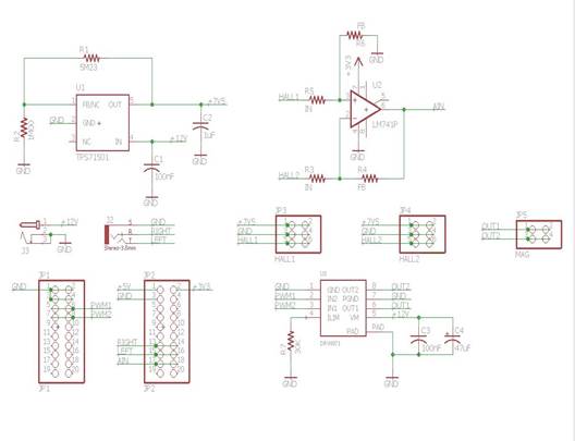
New schematic
Figure 5. Comparison of experimental setup and equivalent schematic to be implemented on a 2” x 2” shield board.
The control code will be moved over to a TI TMS320F28377S single-core Delfino MCU for more powerful floating-point calculations and better ADC sampling. To reduce the size of the system, a small shield PCB will be fabricated for the microcontroller to handle the peripheral requirements needed for levitation. The board will contain a 12V, 1A H-bridge to control the current into the electromagnet via PWM, a small power circuit to supply the Hall effect sensors with a constant 7.5V input, and a differential operational amplifier circuit to take the difference between the sensor readings. It will also include an audio jack, so music can be sent to the controller for beat detection.
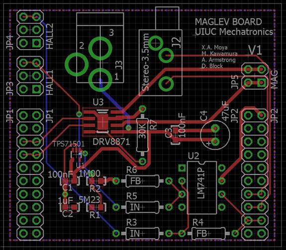
Figure 6. EAGLE layout of the Maglev board.
The Maglev will also be moved to a new tripod-style stand, which serves two purposes: a more aesthetically pleasing levitation experience, and an improved method of gripping the electromagnet which allows the Hall effect sensors to be glued along its central axis, ensuring the most accurate field measurements when sensing the position of the floating magnet.
Figure 7. Solidworks rendering of the improved Maglev stand.
With these improvements, we should be able to achieve a functional levitation system with beat detection in a compact package.
Group Members:
Ashley Armstrong Malia Kawamura Xavier Moya


Acknowledgements:
Dan Block Spencer Kieffer