The Iron Giant
GE 423
The Team
Susan Chen
Jake Haynie
Rahul Shah
Nathan Zimmerer
The Strategy
Path Planning
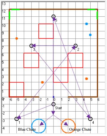
The robot uses an A* path planning algorithm to determine the optimal path from a given start point and endpoint. Kalman filtering is used to merge position data from an OptiTrack camera system and position data calculated from encoders on the wheels. The filtered data provides the robot with an accurate account of its position and orientation in the course. The A* algorithm uses the Manhattan distance to a destination to calculate its heuristic values. The robot does not attempt any diagonal movement, moving solely to tiles that are above, below, or to the side of it. The robot uses data from its ladar as it moves through the course to recognize obstacles. Upon recognizing a newly undiscovered obstacle, the robot updates the map that its path planning algorithm uses and re-plans its path. The robot also will plan a path to the next destination upon arriving at a waypoint. When a blue or orange ball is within view, the robot will turn towards the ball rather than obey its path plan and upon grabbing the ball, the robot will re-plan a path to the destination from its current location.
Obstacle Detection
The robot pre-calculates all the possible obstacle locations in its initialization stage. It stores that data in an array with the robot’s A* coordinates as indexes for easy lookup. It grabs 9 ladar readings every few milliseconds and compares the X and Y position of the location it detects to the all the calculated possible obstacle locations. If the difference between them is more than .25 tiles, then we increase the count of that obstacle location. We keep track of how many times obstacles are seen in order to reduce error. Once we count it more than 10 times, we can consider it an obstacle and set the obstacle array to ‘2’ to mark it as a definite object. Then the map array is edited with the center and two side points of the obstacle.
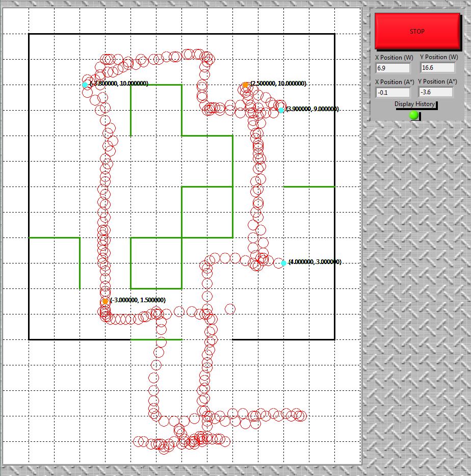
Once a coordinate is marked as a ‘definite object’, it is added to an array to be sent to Labview. Labview is reached through a TCP/IP connection to our computer terminal. When a new obstacle is found, Labview updates that position on the map. Labview determines if the obstacle is a horizontal or vertical wall based on the x coordinate. We know that all obstacles centered on even numbers are vertical walls and odd numbers are horizontal walls. Then labview updates the display with a green line to indicate a wall.
Ball Detection
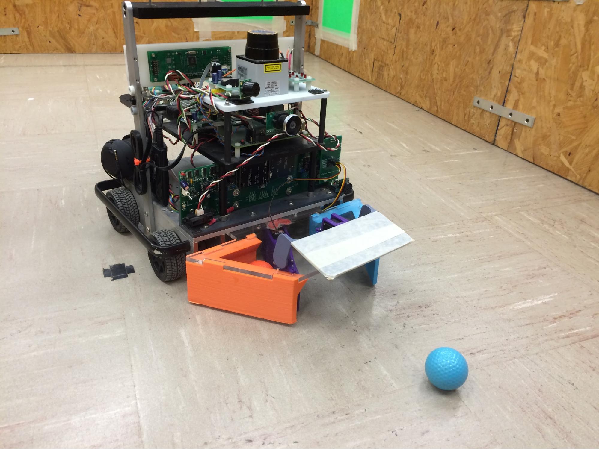
The robot is able to do ball detection through the use of the ColorVision.c file which uses image processing of what the robot sees from the front camera. When the robot has seen 15 pixels of either orange or blue, it has detected the ball, from there we set a flag to tell it to approach the ball at a certain speed.When the robot gets close to a ball, the gate opens and moves the flap to the corresponding color that the robot detects. Once the ball is out of the camera’s view we set the robot to timeout for 750ms and continue going in the direction where it last saw the ball; once that has been done the gate will close to properly secure the ball. At the moment the gate has closed the location of the ball is sent to LabView. Labview reads the coordinates of each ball, and displays them on the map in the ball’s color. The coordinates are also displayed next to the ball to ensure proper accuracy of the display.
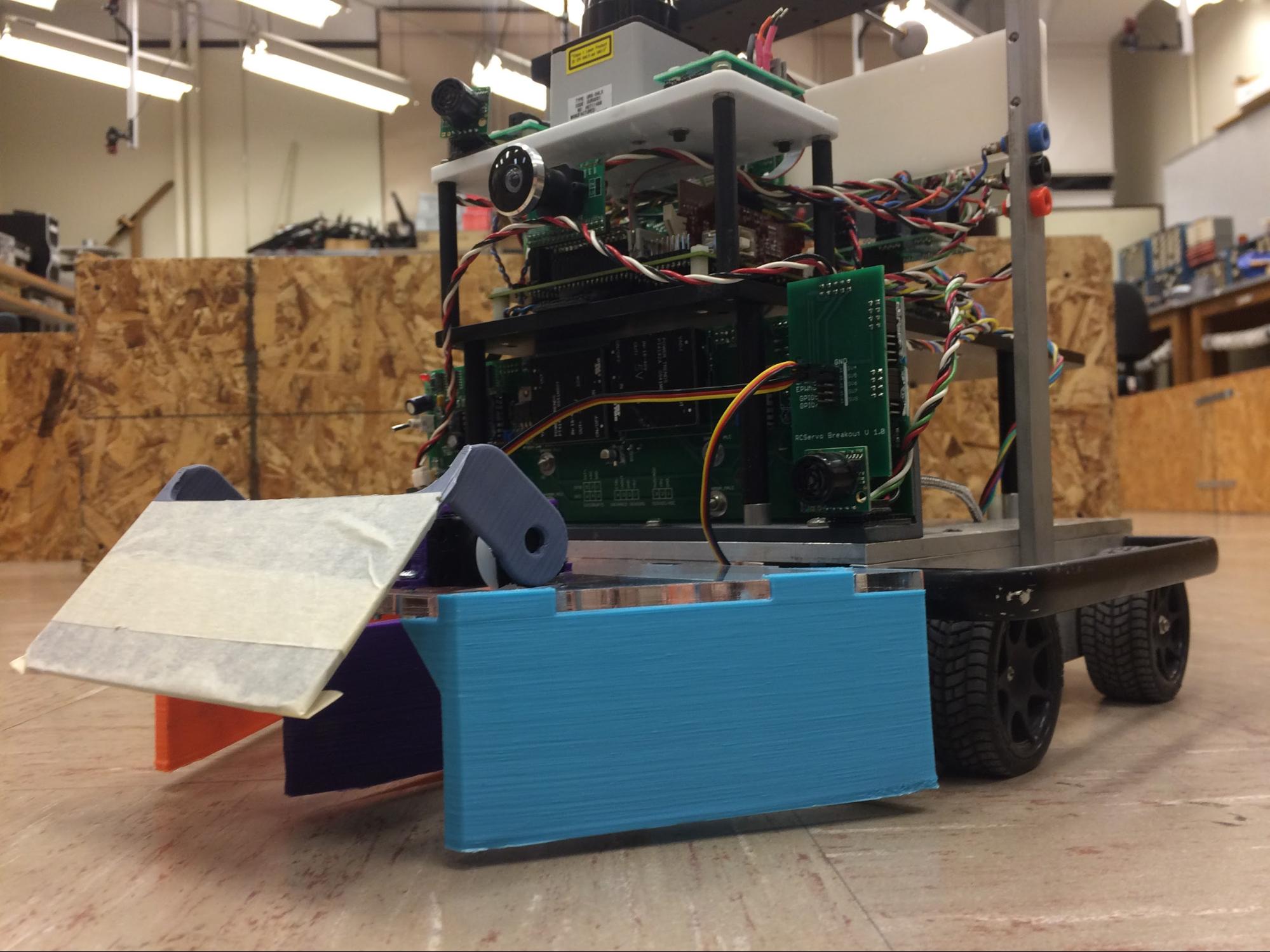
The ball collector was custom designed in the Mechanical Engineering Innovation Studio. The plate was laser cut from acrylic and all other parts were 3D printed on the Studio’s printers. The collector has one gate and one color selector. The gate moves up and down to allow balls to enter/exit, and the selector moves left/right to sort the balls as they enter the gate.
For the gate logic, we set the robot to change the servo’s degrees from a value of 4 (being closed) to a value of 9 (being open). The way we implemented when to open the gate was creating a specific flag for each color when a ball is close(ball-close flag), from there we changed the value of the gate to open while the robot was in a timeout going towards the ball. As mentioned earlier, once the timeout has finished the robot would have its ball-close flag to low indicating the gate should be closed at that instant. The way we decided to separate the colored balls was with a flap to move between two positions depending on which colored ball it was.
One thing that must be noted is that the robot also uses the LADAR to help it move away from obstacles. This is essential for the robot to maneuver around the course properly, as it would make sure not to go to close to an obstacle when trying to collect balls. The benefit of using the LADAR is to make sure when the robot does detect a ball by a corner turn, it does not drive in a b-line direction to secure the ball. Instead what we have done is to make sure the LADAR does not recognize any obstacles in the angle of view that we have set; this ensures that the robot will continue moving until it has properly made sure the path is cleared and then going after the ball.