The goal of the project was to code and modify a robot that could autonomously navigate through a course with previously unknown obstacles, go to certain waypoints, and pick up and deposit blue and orange golf balls into their designated areas.
The robot was a result of multidisciplinary efforts working together to be successful. This included the integration of mechanical, software, and electrical systems.
The robot operation consisted of having a few different systems running together. These include mechanically picking up and depositing different colored golf balls, global positioning, golf ball detection, obstacle detection and avoidance, and navigation.
Mechanical
Strategy
The overall design strategy was to make a ball catcher that could survive ramming into walls and obstacles before the obstacle avoidance code was perfected. Laser cutting was chosen over 3D printing in order to decrease the amount of time to go from a design to a functional prototype. An infrared sensor was attached to the front gate looking down in order to tell when a golf ball passes under the gate, but blindly driving forward for a few seconds worked well enough. We ran out of time to implement the sensor in software.
Design
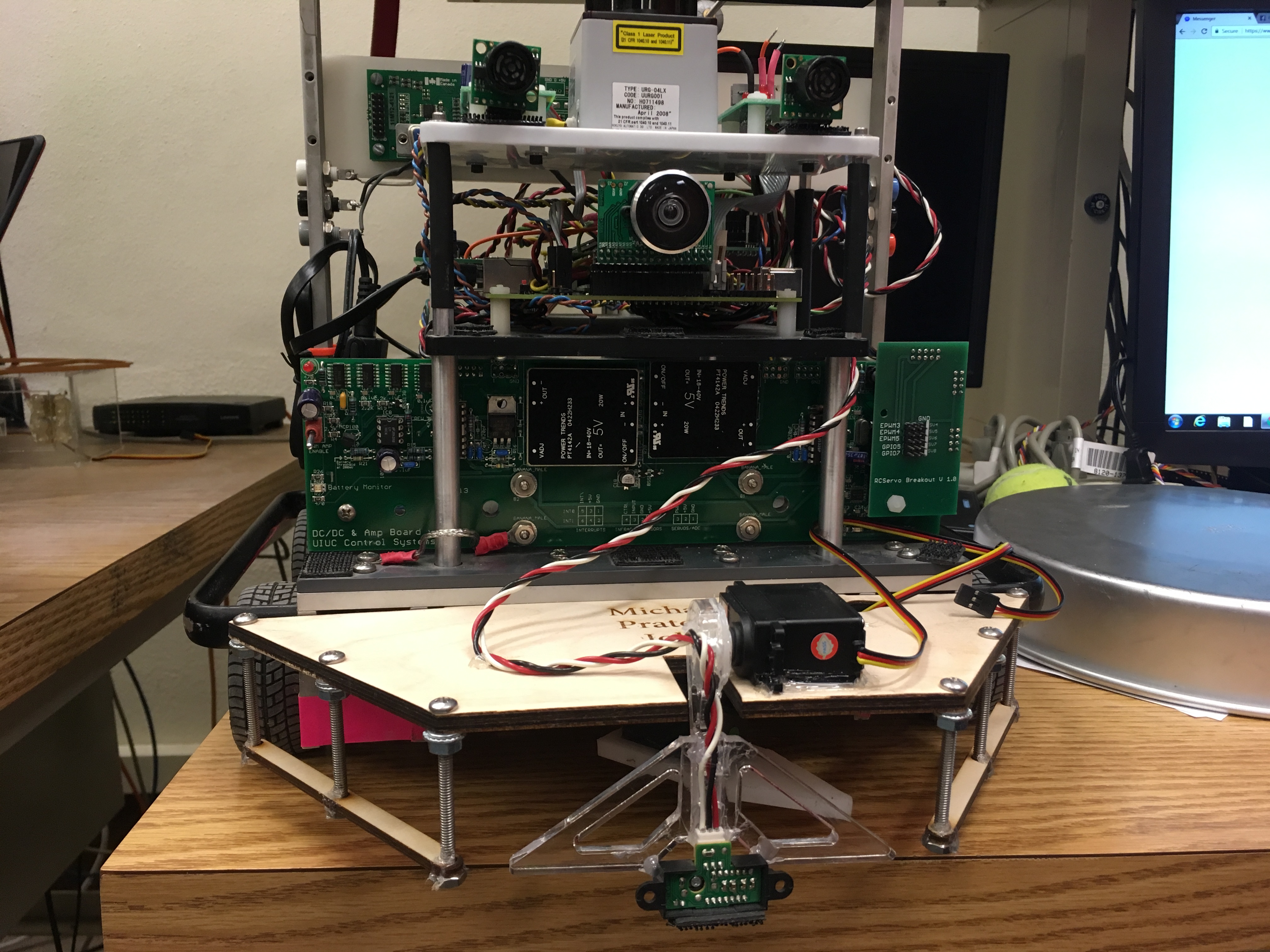
We opted to laser cut our front bumper from wood to ensure our hole measurements were correct. The balls were trapped underneath with rails made from long bolts and more laser cut wood. A tongue made of laser cut acrylic and a servo separated the balls into different compartments. The door at the front, laser cut from two pieces of clear acrylic, was opened by a servo. All of the components were within the front bumper, normally a machined piece of white plastic for other teams. We did not have to fix or replace any parts throughout testing or the competition.
Global Positioning
For our robot to know it's location in the world coordinate frame, we it needs to track it's movement over time. Because the robot's gyroscope samples at discrete intervals, and because wheels may slip, the position of the robot will become increasingly inaccurate as time progresses. To counter this, we use multiple position tracking mechanisms to get a more accurate position of the robot.
Dead Reckoning
The simplest form of position tracking was used on the robot for dead reckoning. By tracking the angle of the wheel by using the motor's encoder, the distance traveled by the wheel can be determined. Because the robot rotates about its center, the two calculated distances can be averaged to determine the overall distance traveled. Using a gyroscope and using a discrete integration over time, the robot's angle, relative to its starting position, can be determined. This angle, paired with the incremental distance traveled, and some basic trigonometry, can determine the robot's position in the global coordinate frame.
Motion Capture
The motion capture system uses infrared emitters and cameras to track the position of reflective markers on the robot. The motion capture system can provide the global coordinate and orientation of the robot.
Kalman Filter
To merge the two locations provided by the two positioning methods, a Kalman Filter was used. The Kalman Filter used a prediction scheme where the dead reckoning was seen as 4 levels of magnitude more certain.
Golf Ball Detection
A total of 5 orange and blue golf balls were placed on the course. Because the location of the golf balls was unknown to the robot, it must detect a golf ball in the course and properly identify it as blue or orange. It must then detect the position of the golf ball so that it can be retrieved.
Camera Input
The camera records an image using the BAYER pattern. The image is then converted to an RGB image for processing.
HSV scale
To easily identify the color of an object, the RGB image was converted into an HSV image. This allows colors to easily be detected as similar colors will have a smaller difference in their hue.
Raster Scan
To detect objects, a raster scan was performed on the image. The first scan produced an incomplete list of connected components. While all components were identified, they may have been counted as multiple components due to a single component being segmented into multiple ones due to its geometry. A second pass through the image reduces the number of connected components to its correct value. Because the upper half of the image contains the ceiling lights and optitrack cameras, it introduces false positives of golf balls. To prevent this, only the bottom half of the image was processed.
Position Information
After the largest object has been identified, the centroid and number of pixels is reported.
Timing Limitations and Other Modifications
Due to the image processing algorithm consuming a significant portion of time, only one color can be scanned at once. To mitigate this limitation, the colors were scanned alternatively, effectively reducing the sampling rate by a factor of two.
Obstacle Detection and Avoidance
Because the location of obstacles in the course is unknown, the robot must actively look for obstacles to avoid them.
LADAR Readings
To detect obstacles in the course, a LADAR sensor was used. Through the LADAR sensor, over 200 distances to obstacles around the robot could be determined. Using theses distances, along with the position and orientation of the robot, the global coordinates of obstacles could be determined.
Obstacle Mapping
Once an obstacle had been detected and its centroid calculated, the obstacle map would be updated to reflect the change. To do this, all possible obstacle locations were stored on the robot. When an obstacle was detected, the robot would iterate through all possible obstacles and determine which of the possible objects was detected. To determine if a possible object was detected, the global coordinate of the detected object must fall no more than 0.15 tiles (feet) away from the wall object, and 0.5 tiles (feet) of the center of the wall.
Reducing False Positives
To reduce the number of false positive obstacles, two methods were used. First, an object must be detected at least 5 times before it is officially detected. Secondly, obstacle detection is disabled when the robot turns more than 60 degrees per second.
Navigation
The robot must successfully navgate through the course and avoid all obstacles while doing so. To achieve this, a path planning algorithm must be used.
A* Path Planning
The A* path planning algorithm was chosen as it is relatively simple and was covered in class. The A* path planning algorithm iterates through possible paths from a start position to a target position, and chooses the shortest possible path that avoids obstacles.
Switching between Golf Ball and A*
To retrieve golf balls, the robot must exit its path planning algorithm momentarily until a golf ball is retrieved, and then return to the path planning algorithm. This switch is made once a golf ball is detected. Once a ball is detected, the robot uses a proportional controller to rotate such that the golf ball is centered in its view. At that point, the robot moves forward, opens the front gate, and closes the gate when ball is below the front bumper. At this point, the robot is in a new position; the A* algorithm is rerun to allow the robot to properly plan its path to its next destination.
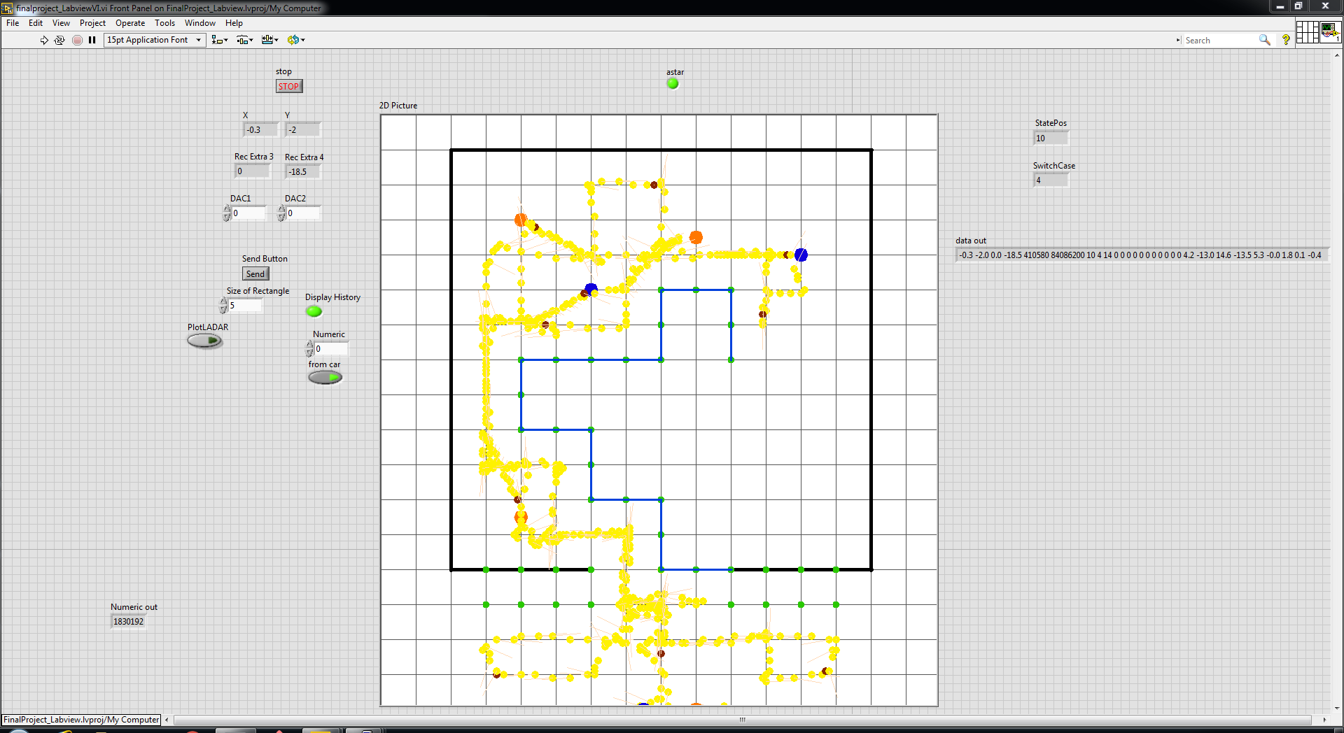
LabVIEW Interface
To allow for visualization of the robot and the course, a LabVIEW GUI was developed. The LabVIEW GUI displays the position of the robot, the positions and colors of retrieved golf balls, and the positions of detected obstacles.
Results
Our robot was able to successfully navigate, identify, retrieve, and deposit all five golf balls, along with avoid contact with all walls and obstacles. Unfortunately, in a few difficult course layouts, our robot would not be able to retrieve nor identify a golf ball which it would never cross paths with. Furthermore, our robot's timing was a bit on the slow side.
Future Work
Spend more time figuring out how to implement the infrared sensor on the gate looking down. The goal would be to tell when a golf ball passes under the front gate after it goes out of the view of the camera.
It would be fun to project a red laser grid onto the course in front of the robot to find walls and obstacles using a better camera instead of the expensive LADAR system.
It would be nice to speed up our robot and to have it explore additional locations on the course if had reached all waypoints but not retrieved all golf balls.