Building a Segbot (with a Completed Board)

<- Previous Step    Next Step ->

Making the Wires and Connectors

In order to connect the external sensors and the motors to the main board, you will need to make the necessary connectors to plug in to the correct headers.

Right Motor

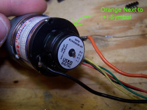
Measure out two 6'' lengths of about 22 gauge wire, one orange and one black. Use a wire stripper to strip about a quarter inch of wire from one end of each. Twist the wire strands. These two wires will power the motor. Connect the orange wire to the motor by looping the twisted wire strands through the motor connector that is next to the (+) symbol. Loop the twisted wire strands of the black wire through the other motor connector. Your connections should look like those in the picture below.


Using a liberal amount of solder, secure the connections by soldering the wires to the motor connectors. The result should be similar to below:


Next, straighten the orange and black wires out along each other with the smaller guage wires of the encoders. Cut the encoder wires to a length about equal to the lengths of the orange and black wires connected to the motors. Crimp large pin connectors to the end of each wire. If you are not sure how to crimp correctly, please read the crimping guide. Plug the wires into a 3x2 connector (you may have to use clippers to cut down a larger connector) according to the diagram below. Also, the resulting connector is pictured. If you find that the wires are not securely snapping into the connector, first make sure they are orientated correctly (small tab on the crimp facing out). If that doesn't work, use a pliers or tweasers to bend out the small tab on the crimp.


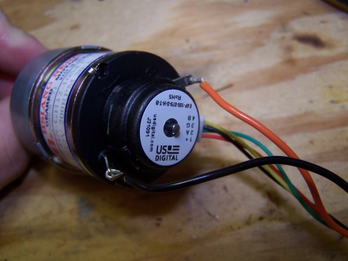
Right Motor Connector (SV3)


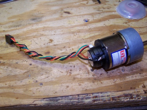
Right Motor Assembly

Left Motor

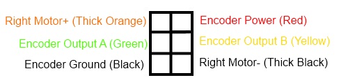
To make the connector for the left motor, follow the same steps as for the right motor. However, when plugging the wires into the 3x2 connector, use the diagram below.


Left Motor Connector (SV4)

IR Sensors

To make the connectors for the IRs, you will need to measure out four 10'' lengths of wire (two black, one white, one yellow). Measure out two 12'' lengths of red wire. Strip both ends of each wire. Taking one red wire, one black wire, and the white wire, attach small crimps to one end of each. Next, place those small crimps in the small IR connector. Do the same for the other three wires. The only difference should be that you use the yellow wire in place of the white wire. The correct order and results should look like the following.


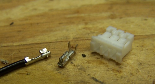
Small Crimp / IR Connector


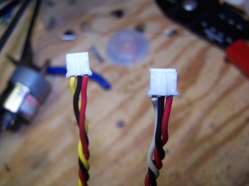
Correct IR Connectors

After you have made the connectors for connecting to the IRs, crimp the other end of the red wires, the yellow wire, the black wires, and the white wire using the larger, standard crimps.

Create the connector for the ultrasonic sensor by measuring out four 6'' lengths of wire (one black, one red, one green, one blue). Strip a small amount off of both ends of each wire, crimp the normal crimps onto each end of every wire, and install the wires into a 5x1 connector according to the following diagram.


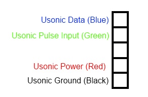
Ultrasonic Connector

At this point you should have ten unconnected wire crimps. Install them into two 6x2 (SV9 and 12) connectors and a 3x2 (SV10) connector according to the following diagrams.


<- Previous Step    Next Step ->

Home ♦ Updates ♦ Videos ♦ Contact Information 

Construction Navigation


Precision. Accuracy. Speed.

University of Illinois at Urbana-Champaign Logo Control Systems Instructional Laboratory
University of Illinois
at Urbana-Champaign
1406 W Green
Urbana, IL 61801-2307