Soldering a Segbot Board
Next Step ->
Soldering on a FT2232D
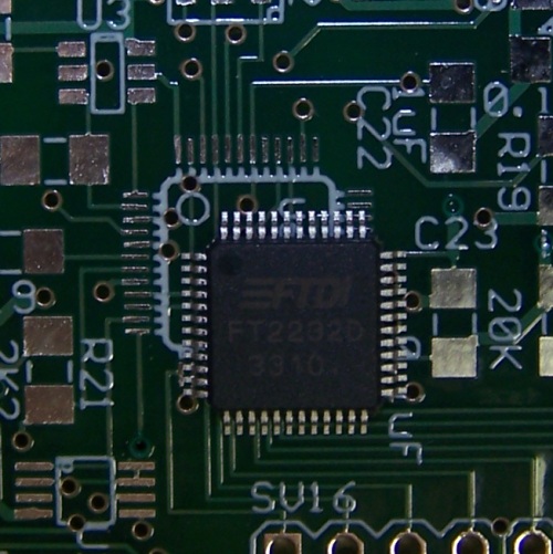
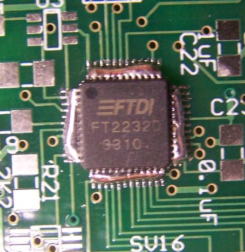
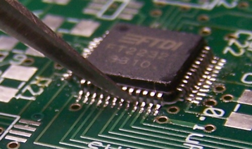
Pictured below is the FT2232D USB UART/FIFO IC. This chip is the most difficult item to solder on to this board. As a general strategy, we like to align the chip correctly, hold it in place, solder all of the pins together, use solder wick to remove the excess solder, and then touch up any pins that may be soldered too much or not enough. This process is outlined on this page.
Below the correct orientation of the chip is shown. Simply make sure that the corner of the chip with the circle is in the same corner as the circle on the silkscreen.
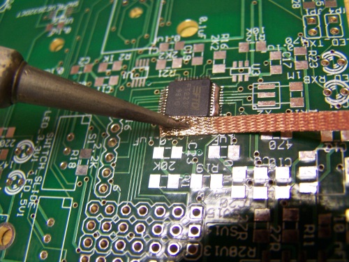
Begin by bending the end of the solder strand up so you will later be able to apply solder to the end of the iron using only one hand. Once you are sure the chip is on the correct way (the circle positions agree), align the chip such that all of the pins line up with the solder pads. Do this by pushing the chip around with the tweasers and then pressing down on the chip with either the tweasers or a finger once it is positioned correctly. If the chip moves when you press down, try again. You can also try pressing down with your finger or the tweasers, and then moving or rotating the chip with your other hand until it is in the correct position. Either way, once you think all the pins are aligned well, look very closely or use the magnifying glass to check your work. Next, without moving the chip, apply a liberal amount of solder to the iron, and solder a few adjacent pins on the chip. Before taking pressure off the chip, add some more solder to the opposite side of the chip. Remove the pressure and check to see that everything still looks aligned well. It should look something like below.
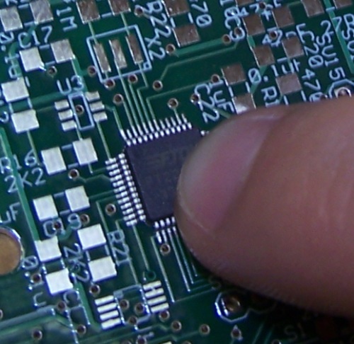
Pressure from Finger
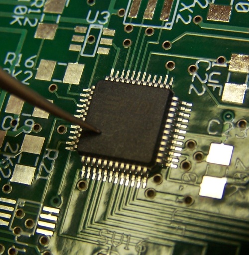
Pressure from Tweasers
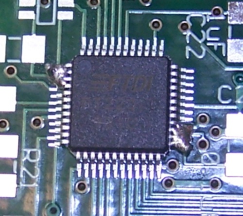
Initial Soldering
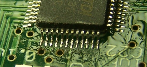
Next, on each side of the chip, heat up the pins and feed solder such that all of the pins are connected. The result should look like the following.
For each side, use the solder wick to remove most of the excess solder. This process and the results are pictured below.
Wicking Up Excess Solder
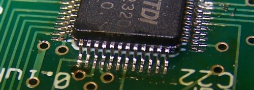
Result of Solder Wicking
Run the soldering iron tip between each neighboring pin from the top of the pin to the bottom toward the solder pads. This will spread the solder out evenly and will help make it more apparent if any two pins are connected that should not be.
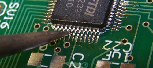
Examine each pin. Every pin should appear shiny. If there is any pin you think is not soldered correctly, heat it and apply a very small amount of solder. If you accidentally connect pins, use the solder wick to clean up the excess solder. Again, after you have added solder, run the iron's tip between the pins near where you added solder. Once you think everything is soldered correctly, use the tweasers to apply a small amount of force to each pin. If a pin bends, carefully bend it back and add solder to make sure it is connected. Checking the pins with the tweasers is shown below.
A resulting side of the chip should appear something like the following. You can see that I slightly bent one of the pins, but that should not be a problem.
Once you are confident you have soldered this chip correctly, move on to the next step.
Next Step ->
Home ♦ Updates ♦ Videos ♦ Contact Information