Soldering a Segbot Board
<- Previous Step Next Step ->Soldering the Headers
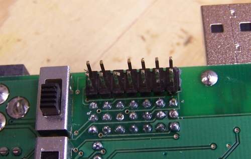
Finally, you will need to solder on all of the headers. You can either decide to solder on the bare minimum headers required to get the Segbot running, or you can choose to solder all of them (or whatever you think you will need). Pictured below are the minimum headers required to get the Segbot running. You will need to solder female headers for the silkscreen labeled POLOLU_LPR510AL and POLOLU_MMA7361. Male headers are required for SV2 (the external JTAG connector, not labeled on the board), SV3, SV4, SV9, SV10, SV12, and SV13-15. When you solder SV2 at the top of the board, make sure solder it such that the pins are on the back of the board (this is pictured).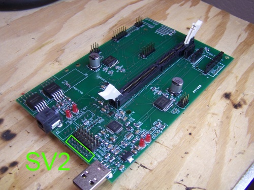
Minimum Headers
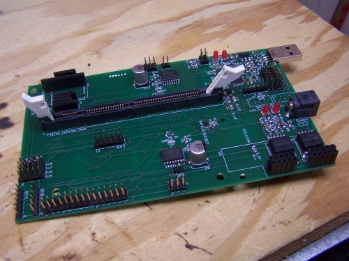
All Headers
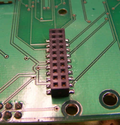
Pin 6 Removed
University of Illinois
at Urbana-Champaign
1406 W Green
Urbana, IL 61801-2307