Soldering a Segbot Board
<- Previous Step Next Step ->Soldering the Other Chips
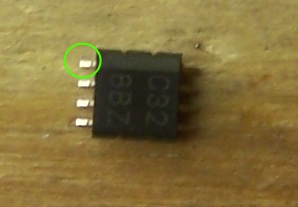
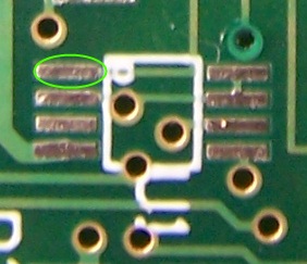
Now is a good time to solder on the other chips. The flip-flop, the dual OR gate chip, the EEPROM, the TLV1117-33CDCYR, and the motor driver PWM ICs all need to be placed on the board. Each can be soldered similar to how you soldered the FT2232D, or you can try to solder them one pin at a time. Soldering one pin at a time should be relatively easy for the two A3953 motor driver chips, and slightly more difficult for the other three chips. For these chips, it is important to place them correctly on the board. Following is a guide on how to match pin one on the board to pin one of the chip. The marker on a chip or the silkscreen marker on the board may either be a small dot in the corner, a bar at an end or side, or a rounded notch at the end of a chip. Each one is pictured below with pin number one identified. The marker on the EEPROM chip is a very small dot that indicates the first pin. On the board, the first pin is indicated by an end bar marker. For this type of marker, the first pin is the pin at the left end of the bar.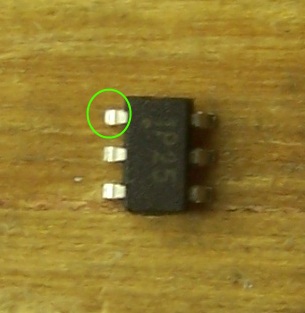
EEPROM Chip
EEPROM Silkscreen
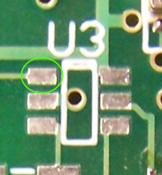
F-F/Dual OR Package
F-F/Dual OR Silkscreen (F-F silk pictured)
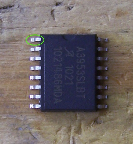
A3953 Chip
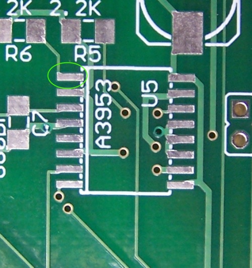
A3953 Silkscreen
University of Illinois
at Urbana-Champaign
1406 W Green
Urbana, IL 61801-2307