Building a Segbot (with a Completed Board)
<- Previous Step
Next Step ->
Preparing the Board
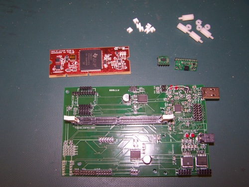
Pictured are all of the components required to prepare the board for installation into the Segbot. You need a soldered board, a modified controlCARD, one accelerometer, one gyroscope, four plastic pins with nuts, and seven small jumpers.
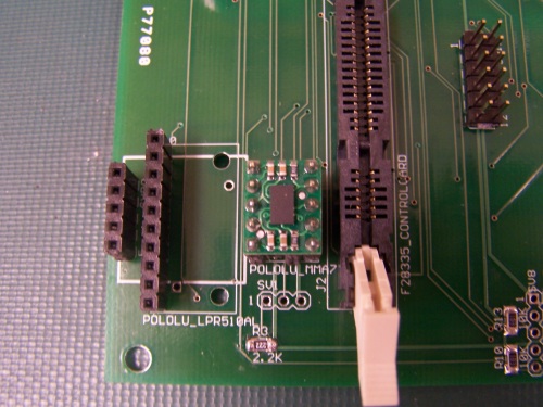
In order to prepare the board for installation into the plastic shell, open the white tabs on the DIMM connector, firmly place the controlCARD into the slot, and close the white tabs. Next, place the gyro and the tilt sensor into their respective headers (note the silkscreen outlines of the sensors). A picture of the correct orientation of the tilt sensor is shown below.
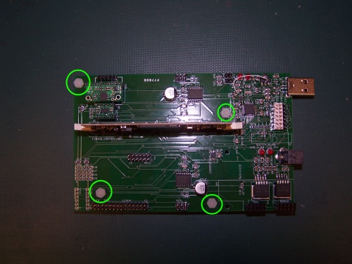
Finally, screw the four plastic pins into the board so that the long side is on the bottom of the board. The correct locations for these pins is visible in the following picture.
The final step is to set the JTAG jumpers correctly. If you want to use the XDS100, connect the bottom two rows of pins. If you want to use another JTAG Emulator such as the XDS510LC, connect the top two rows of pins. The jumper pins and an example connection are shown below.
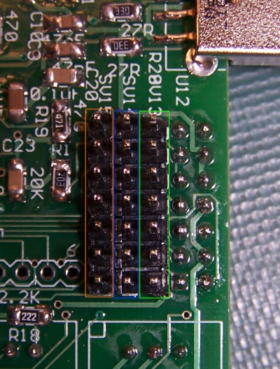
Orange: XDS100; Blue: Connections to controlCARD; Green: Offboard Emulator
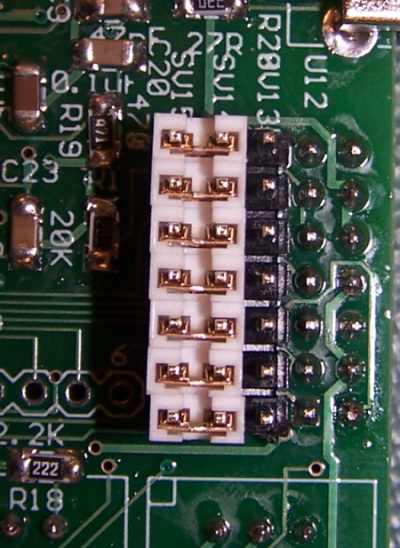
Example Setup for XDS100
Once you have done this, the board is assembled and is ready to be installed into the plastic shell of the robot.
<- Previous Step
Next Step ->
Home ♦ Updates ♦ Videos ♦ Contact Information