Building a Segbot (with a Soldered Board)
<- Previous Step
Next Step ->
Preparing the controlCARD
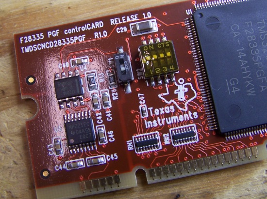
Since we are using the XDS100, and more specifically the FT2232D FTDI chip as a USB to serial adapter and not the on-card RS232 transceiver, we need to modify the default state of the controlCARD for our setup to work correctly. If you are using a newer F28335 controlCARD, either the TMDSCNCD282335 R2.2 or TMDSCNCD28335PGF R1.0, you will have a switch on your daughter card, SW1, that needs to be switched off. Change the dip switch to the off position. On the TMDSCNCD28335PGF R1.0, the correct position is shown below.
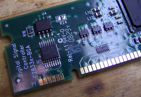
If you are using an older controlCARD, TMDSCNCD282335 R2.1 or older, you will need to remove a resistor from the daughter card. Remove R24 from the board by heating up both of the solder pads and pushing the resistor off. Make sure there is no solder connecting the two pads. The location and the removed resistor are shown below on a TMDSCNCD282335 R1.1 controlCARD.
Once you have completed one of these two steps, your controlCARD is ready. However, now is a good time to figure out what speed crystal your controlCARD has. To check, find "X1" on your controlCARD (it should be very close to the F28335). Look closely and read the resonator. If you can't see it well enough to read, use a magnifying glass. It should read something like "30.000" or "20.000." This number corresponds to the frequency of the crystal's oscillations in MHz. Take note of this number.
<- Previous Step
Next Step ->
Home ♦ Updates ♦ Videos ♦ Contact Information