Building a Segbot (with a Completed Board)
<- Previous Step
Putting It All Together
At this point, you should have completed everything in the picture below. You should have the mostly assembled shell, all of the crimped wires and connectors needed to attach the motors, the IR sensors, and the ultrasonic sensor to the board, and a prepared board with the controlCARD and the gyro/accelerometer attached. Additionally, you should have the battery, the wheels, and the 6mm hubs for attaching the wheels.

Before you move on, attach a few pieces of velcro to the top of the Segbot. Rig something with the velcro that looks similar to the pieces shown in this picture:
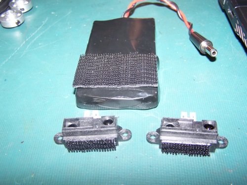
Next, you need to attach velcro to the IR sensors and the battery. Attach small pieces to the bottoms of the IRs and attach a larger piece to the battery. Reference the picture below.
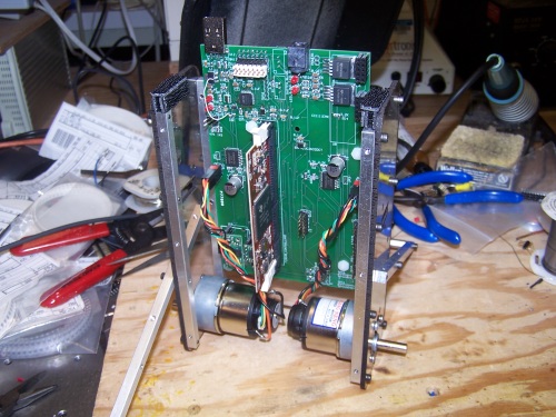
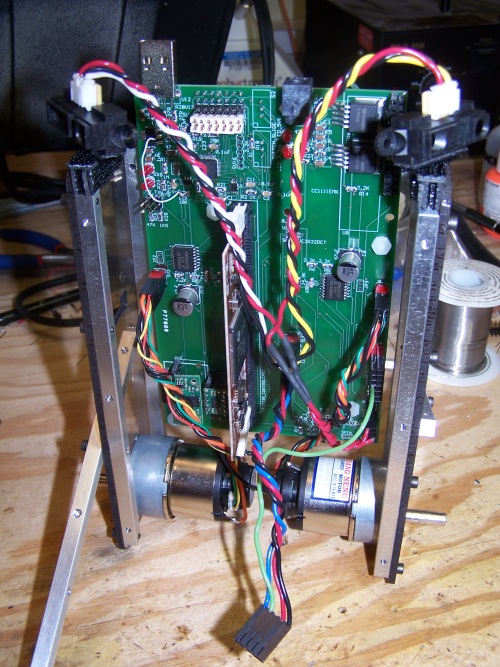
Attach the prepared board to the back plate of the plastic shell using the short 3/32'' hex screws (you can also use other types of short 3/32'' screws). Plug the motor/encoder connectors into the board once it is attached. The Segbot's right motor connector should plug into SV3 on the board and the left motor's connector should plug into SV4. The attached board and the plugged in motors are shown below.
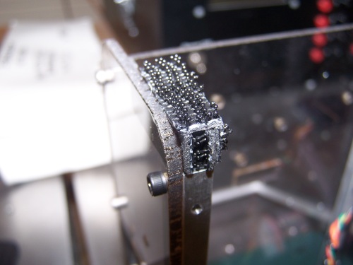
It is very important to make sure that the motor connectors are attached correctly and not flipped. Close ups of the header connections and attached connectors for both headers are shown below. Make sure your connections match precisely. Once you are sure they are plugged in correctly, use a paint marker (or two - one color for each side) to indicate on the connector and the board how the connectors should be orientated. This is also pictured below.
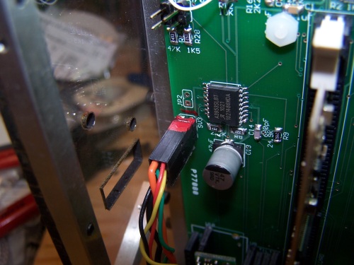
SV3 = RIGHT MOTOR
SV4 = LEFT MOTOR
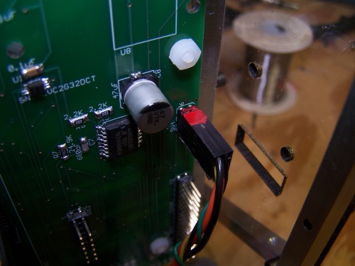
Next, attach all of the connectors you made for the external sensors. The connector with the two red wires for 5V power to the IRs should be plugged in to SV10, and the larger double connector should be plugged in to SV12 as shown. Mark the board and the connector with a paint marker. Place the left IR (one with yellow data wire) to the left side of the Segbot, and place the right IR (white wire) to the right side of the Segbot. At this point, the assembly should appear as in the pictures below:
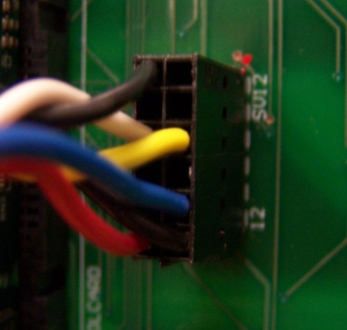
SV12 Connected
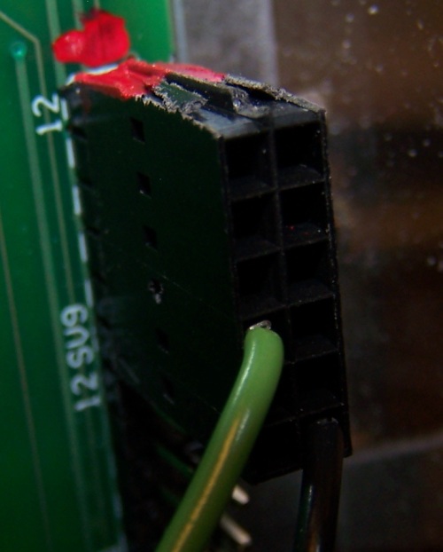
SV9 Connected
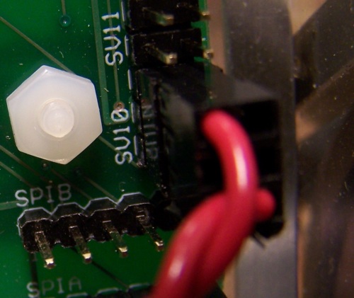
SV10 Connected
Attach the front panel of the plastic shell by first pulling the ultrasonic connector through the square hole in the panel, and then by screwing six 3/32'' hex screws into the aluminum bars. Attach the ultrasonic sensor and mark it with a paint marker as shown below. The connected ultrasonic sensor should appear as shown below:
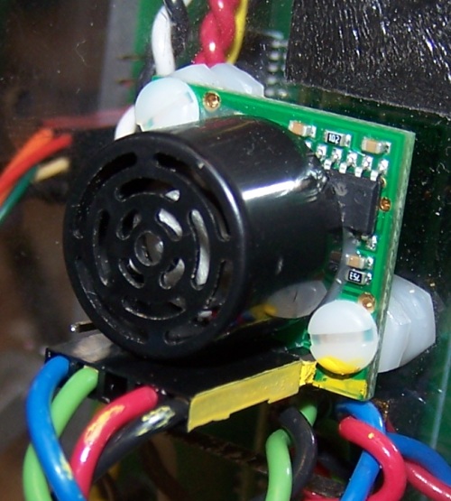
USonic Sensor Connected
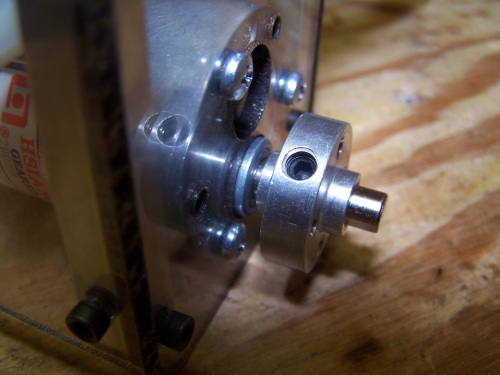
Next, attach the 6mm hubs to the motors. Make sure that the hubs are close to, but not touching, the side panels of the shell. Once it is in position, tighten the hub using a 3/32'' hex key. Check to make sure your hubs are attached as shown below, and then move on to the next step.
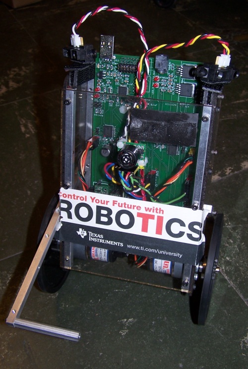
Finally, attach the wheels to the 6mm hubs using two 3/32'' hex screws per side. The fully assembled Segbot should appear as in the picture below (only without the TI decal). At this point, the Segbot is fully assembled, and you are ready to move on to
programming the Segbot.
<- Previous Step
Home ♦ Updates ♦ Videos ♦ Contact Information