Soldering a Segbot Board
<- Previous Step
Next Step ->
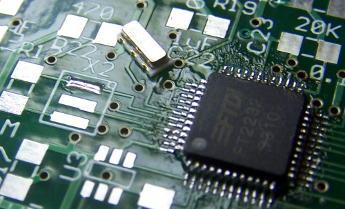
Soldering the Resonator
Below is the 6MHz resonator. It needs to be soldered near the FT2232D to provide a good clock to that chip. Begin by adding some solder to one of the end pads. This is also shown in the picture below.
Next, with the soldering iron in one hand and the tweasers in the other, heat up the presoldered pad by touching the iron to the very end of the pad (pictured), and guide the end of the resonator onto that pad. It does not matter which end of the resonator goes on which pad. Once the resonator looks straight and centered over the three pads, press down lightly with the tweasers briefly and remove the soldering iron. The result should look similar to the following picture. You should clearly see solder on both sides of the resonator.
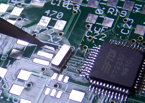
Heating the Pad
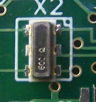
Resulting Solder
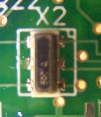
Solder the other two pads by placing the iron at the ends of the second and third pads and feeding solder until you see the solder flow through under the resonator to the other end of the pad. This works best if you feed the the solder to the bottom of the iron by sliding the solder strand flat along the board. When you are done, the soldered resonator should look like the following. You should clearly see solder at both ends of each pad.
<- Previous Step
Next Step ->
Home ♦ Updates ♦ Videos ♦ Contact Information