Building a Segbot (with a Completed Board)
<- Previous Step Next Step ->Wireless Options
There is a variety of wireless options available for the Segbot. You may use the CC1111EMK868-915 Evaluation Module Kit to allow remote control of the Segbot by the eZ430-Chronos-915 watch, you may use AeroComm 4490-200A RF transcievers and the custom AeroComm PC Interface board for a wireless serial connection (you will need to have this fabricated: more info), or you may choose to use no wireless at all. If you decide to use wireless, you should decide at this point whether you want to be able to use the Chronos watch or if you want to use the AeroComm devices. Since both devices operate at 915MHz, we have found that it is best to use only one type of wireless at a time due to interference. If you are chosing not to use wireless, skip to the next step. Otherwise, see one of the options below.AeroComm
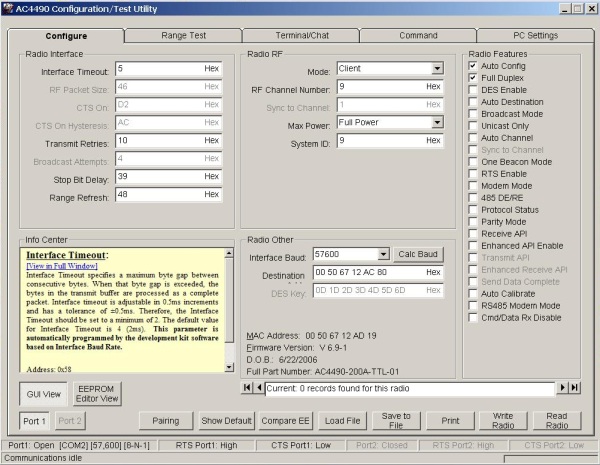
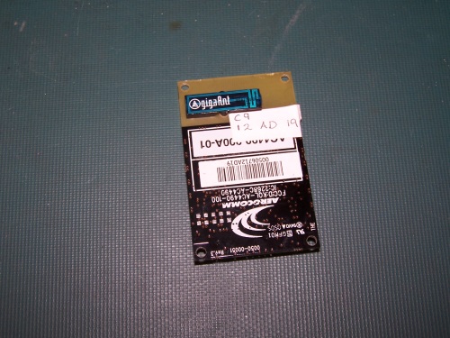
In order to use the AeroComm wireless modems, you will need to have an AeroComm AC4490 PC Interface card made. Please see this page for more information on getting that fabricated. Once the interface card is constructed, you will need to program both of the AeroComm devices so that they communicate properly. In order to do this, you will need to download the "Configuration Utility" from the Software Downloads category of this page. Once you have the program installed, insert one of your AC4490 cards into the interface board, and then power the the board. Open the installed program and go to the "PC Settings" tab. Once there, make sure "USB / Comm Port" is selected under the Port1 Settings box. With the correct port selected and the other settings as shown in the following screenshot, click "Open Port."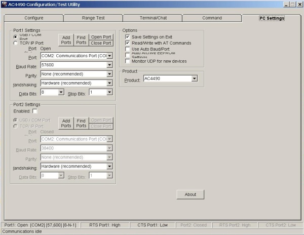
CC1111 Wireless and Chronos Watch
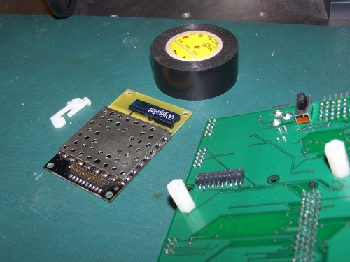
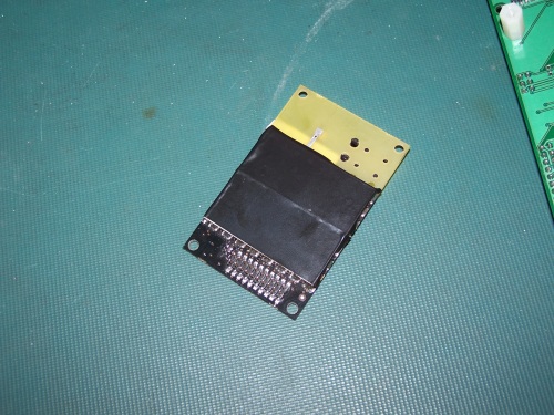
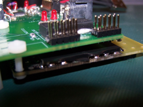
In order to use the CC1111 Wireless device, you need to be able to program it correctly. At this time, version 8.1 of IAR for Intel-8051 architecture is unable to program this card correctly (see this page for more information). If you have access to a slightly older version of IAR for 8051 architecture (we use IAR v7.67, you need at least IAR v7.51A), you may still be able to program the device. If you don't have access, because the most recent free Kickstart version is the only one available from IAR, contact us and we will program the device for you using our equipment. If you want to try to program it yourself with an older version of IAR, you will need a CC Debugger from TI. Our project code is available for download here. The code is a modified version of TI's default project. To install the CC1111 after it has been correctly programmed, simply plug it in to the "Test" and "Debug" headers at the top right corner of the main board. It should appear as it does in the picture below.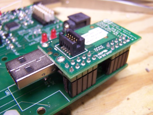
University of Illinois
at Urbana-Champaign
1406 W Green
Urbana, IL 61801-2307